|
|||||||||||||
 |
|||||||||||||
Standing Waves: Do They?
|
|||||||||||||
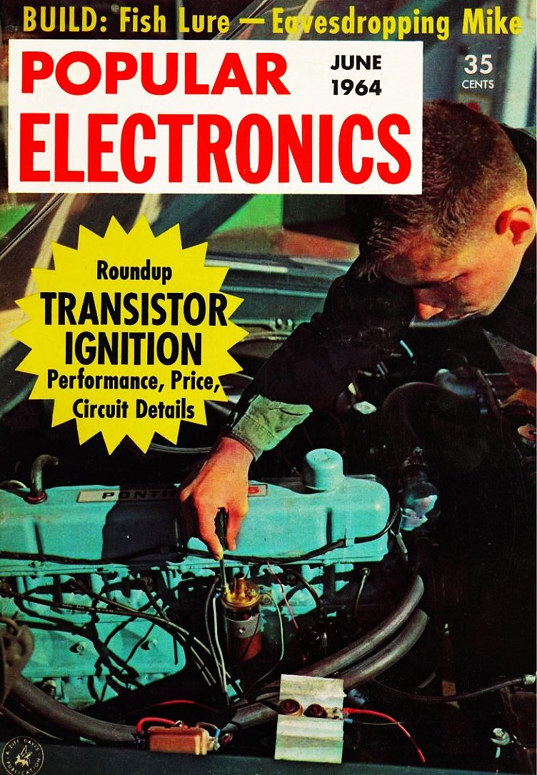
One of the best visual devices for use in demonstrating standing waves resulting from an impedance mismatch is the Shive Wave Machine, developed by Bell Telephone Laboratories' Dr. John Shive. Reflections of waves in a transmission medium can be demonstrated in something as simple as a rope that is terminated on one end, and moved back and forth or up and down at a rate that causes a visible standing wave along its length. You probably did it as a kid with a jump rope (well kids in my era did, back when we played outside all day). I have also seen standing waves demonstrated using a pipe with many tiny holes drilled in the top of it, with propane being fed into it in pulses. A flame is lit at each hole, and then the maximum and minimums of pressure are indicated by the height of the flame. Fred Blechman does a good job of explaining the phenomenon in RF transmission lines in this 1964 issue of Popular Electronics magazine. Standing Waves: Do They?
Sure they do! But don't go and blame high VSWR for your troubles-there are other factors involved.
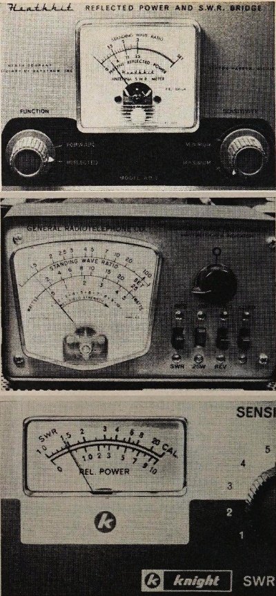
Three different SWR meters were inserted in the same line one at a time. Notice the close similarity in readings that was obtained. The Heathkit AM-2 (top) and the General Radiotelephone Co. 615 are one-piece types in which the transmitter connects to the input, and the transmission line to the output. The Knight -Kit P-2 SWR/power meter has a separate unit that connects into the transmission line; unit shown contains meter and controls. By Fred Blechman, K6UGT If you have been involved with ham, CB or business radio, you may have heard of and wondered about standing wave ratio. There's a profusion of fact and fancy, theory and practice, discussion and argument over this subject. The purpose of this article is to break it down for you and see if we can clear up some of the problems that cause confusion. We'll also analyze a "typical" situation and find out if SWR (or VSWR for Voltage Standing Wave Ratio) is as important as some folks seem to think it is. What Is SWR? Unless you use a handheld transceiver, you have a transmission line to carry the signal from the transmitter to the antenna. The physical construction of the transmission line results in its having a certain impedance at radio frequencies. This characteristic impedance is a fixed value that does not vary with frequency and is one of the two factors that determine SWR. The other factor is the terminating impedance which is produced by the antenna. The antenna also has a characteristic impedance, but this is determined by the type of antenna, method of connection, and frequency of operation as well as other factors. If your antenna impedance is the same as the transmission line impedance, you have what would be a perfect match and your only losses would be due to inherent transmission line losses. More often, a mismatch occurs between the antenna and the transmission line. Now only part of the energy from the transmitter is absorbed and radiated by the antenna. Some of the energy is reflected, or bounced back toward the transmitter. The transmitter continues to push energy toward the antenna, so we have energy going in both directions. The "forward" and "reflected" voltages will combine to produce waves whose crests and valleys do not move along the line, but remain stationary; hence, they are called "standing waves." Standing wave ratio is the ratio of maximum to minimum voltage or current of the standing wave. This is also the ratio of the load impedance (Z1, the antenna) to the characteristic line impedance (Z). Effects of SWR Every transmission line attenuates the signal it carries, due to its ohmic resistance and dielectric losses. As frequency increases, these losses can become quite high. Unfortunately, standing waves increase the attenuation due to the increased current flowing through the transmission line, and the higher-than-normal voltages that can cause more leakage loss. Another sad effect of standing waves is that they reduce the power handling capacity of the line. The allowable power, compared to the rated power, is the reciprocal of the SWR.
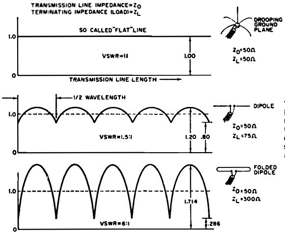
The VSWR is determined by the impedance of the line termination and the impedance of the transmission line as in several examples at left. To simplify things, line losses are not included in figures.
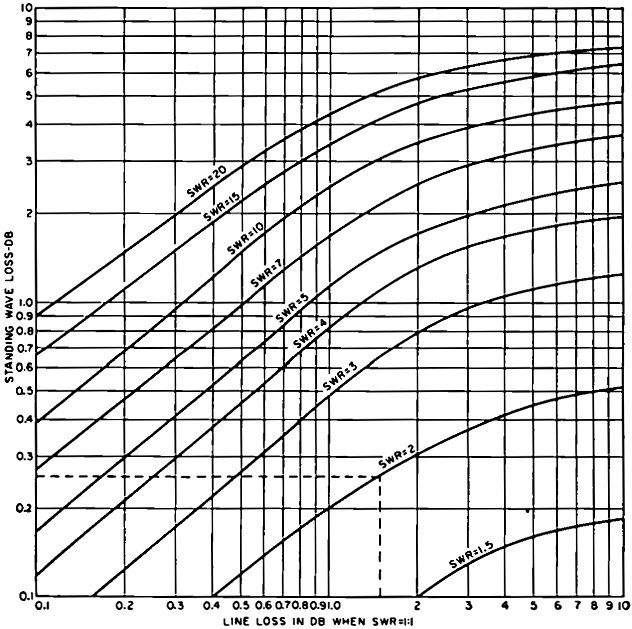
Transmission line power loss is increased with an increase in standing waves. Note that the loss can be more than doubled if high standing wave ratios are on the line.
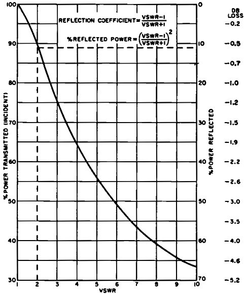
When a transmission line is terminated with a load of larger or smaller impedance than the characteristic impedance of the transmission line, some of the transmitted energy will bounce back from the load to form standing waves. This chart shows VSWR versus power and db loss in transmission line. The most important effect of standing waves, however, is that they indicate a mismatch. Instead of your transmitter pumping all of its power into the antenna, some of this power is reflected back and does no useful work. In other words, reflected power is wasted power. A Typical Example Let's take a hypothetical case, where you have a transmitter with an output impedance of 52 ohms delivering 100 watts to a 150-foot length of RG-8/U at 30 mc. Assume that the antenna impedance at this frequency is 104 ohms. We can look up the characteristic impedance of RG-8/U and find it to be 52 ohms. The SWR is the ratio of the two, with the higher number always the numerator. Here, the SWR is 104/52 or 2:1. The RG-8/U cable also has an attenuation of 1.0 db per 100 feet at 30 mc. at an SWR of 1:1. As you have 150 feet of line, the attenuation i150/100 times one. This equals 1.5 db. Now add the effect of SWR on line loss by looking at the chart on page 64. Locate 1.5 db at the bottom of the chart, go straight up to SWR 2 (actually 2:1), and then to the left to read 0.26 db. This 0.26-db loss is added to the transmission line loss which is now 1.76 db. At an SWR of 2:1, the power loss at the antenna is 0.51 db. The total loss then is 1.76 db in the transmission line, plus 0.51 db at the antenna, or 2.27 db. This means that 59% of your input power is radiated by the antenna. As for the allowable power, RG-8/U is rated for 1720 watts at 30 mc. at an SWR of 1:1. At an SWR of 2:1, this is reduced by 50%, allowing you 860 watts (50% of 1720) which is well in excess of the 100 watts you are putting into the line. What Does It All Mean? How much do these losses hurt your operating effectiveness? A 1.0-db change in signal power at the receiver is considered to be the minimum discernible change. The commonly used industry standard for calibrating S-meters is 6.0 db per S-unit. Receiver sensitivity is usually based on a reference of 10 db signal above the noise level. Actually, a few db of signal is hardly worth getting excited about unless you have some particularly critical requirement. In our previous example, the received signal would be 2.27 db "down," or less than one-half an S-unit, as compared to having a perfect antenna with a lossless line (which doesn't exist). Looking closely, the standing waves contributed 0.77 db (0.26 db plus 0.51 db) loss to the total 2.27 db, and this loss is not even discernible at the receiving end. Are you getting the idea that SWR (if it is reasonably low) is not as much of a villain as you thought? In most practical cases, the majority of loss is caused by the real villain, transmission line loss! However, when your transmission line loss is high to begin with and your SWR is also high, your radiated signal may be really down in the mud. Cure the Cause What to do about SWR? Use the shortest, lowest-loss transmission line you can get, and match this to an antenna whose nominal impedance at the operating frequency is from one-half to two times the line impedance. This will limit your SWR to 2:1. If you can get an antenna with gain, such as a beam - you can more than compensate for both line and SWR losses-since many of these antennas have gains in excess of 8 db. You would have to increase your transmitter power by 6.3 times to get this much gain with a no-gain antenna! The SWR meters are helpful, but don't rush to quote their readings without reservation! The SWR you read at the transmitter is always less than the actual SWR at the antenna. Power reflected from the antenna is attenuated on its way by line loss. By the time it gets to the meter, the reading is always lower than the power actually is. Now you can re-evaluate the importance of SWR. |
|||||||||||||
 |
|||||||||||||
|
|||||||||||||


|
||||||||||||||||||||||||||||||||||||


