|
March 1965 Popular Electronics
 Table of Contents
Wax nostalgic about and learn from the history of early electronics. See articles
from
Popular Electronics,
published October 1954 - April 1985. All copyrights are hereby acknowledged.
|
The first Orbiting Satellite
Carrying Amateur Radio (OSCAR I) was launched on December 12, 1961, and remained in orbit
for 22 days before re-entering the Earth's atmosphere. Fast forward to March 1965
when OSCAR III
was launched on the 9th of the month. That same month this story appeared in
Popular Electronics. This time instead of merely broadcasting "Hi" in Morse
Code, OSCAR III hosted an active relay translator along with a beacon signal.
AMSAT is the
governing body that coordinates and manages amateur satellite operations.
Oscar III: Ham Radio's New 2-Meter Space Station

The latest in a series of amateur-designed and amateur -built satellites
is expected to provide unparalleled DX thrills.
By Robert N. Tellefsen, W7SMC/6, and Harley C. Gabrielson, W6HEK
Of the scores of satellites placed in orbit around the earth during the past seven
years, two were unique. They were built by radio amateurs, they transmitted their signals
in the 2-meter (144-mc.) ham band, and they were observed by a worldwide amateur tracking
network. These first two amateur satellites were named OSCAR I and OSCAR II from the
initial letters of Orbiting Satellite Carrying Amateur Radio. Soon, possibly by the time
you read this, OSCAR III will be in orbit. And, unlike the first two OSCARS which carried
only beacon transmitters, OSCAR III will be a complete 2-meter ham station capable of
receiving and relaying back to earth amateur 2-meter signals!

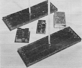
OSCAR III translator with input, output antennas. Three units of translator
(l. to r.) are front end and 30-mc. i.f. strip, up-converter, power amplifier.
Origins of Project OSCAR. The idea of an amateur satellite was put forth by Don Stoner,
W6TNS, in 1959, who pointed out that hams could probably build a satellite "if someone
only had a vehicle" to put it in orbit. Stoner, Fred Hicks, W6EJU, and others developed
the idea and formed the Project OSCAR Association which later became Project OSCAR, Inc.
Typical of the reactions of their fellow San Francisco area hams was a comment by "Chuck"
Towns, K6LFH: "You're crazy. When can we start ?"
The first problem facing the amateurs was what form an amateur satellite should take.
The initial OSCAR concept was a simple beacon transmitting an unmodulated carrier in
the 2-meter ham band. Later, a keying unit was designed to enable the beacon to transmit
the word "HI" in c.w. ( • • • • • • ), and a telemetry channel was added to monitor the internal
temperature of the satellite. "HI" is a friendly greeting between hams, and has the same
meaning in many languages. The "HI" identifier and telemetry channel were used in both
OSCAR I and II.
Construction and Launching
When construction of the first satellite began, many manufacturers
in the space and electronics industries donated hard-to-obtain components that make the
difference between success and failure in a satellite. Other manufacturers loaned test
equipment and gave advice and information. The actual design and construction, however,
were done by hams working in their basements.
One reason for the simplicity of OSCAR I's design was that, although the U.S. Air
Force had indicated a willingness to launch an amateur satellite on a space-available
basis, a final commitment would not be made until the hardware had been built and tested.
A simple design is more reliable, a matter of some importance in a field where Murphy's
Law works overtime. Finally, despite its lack of sophistication, the satellite would
provide tracking experience for future efforts.

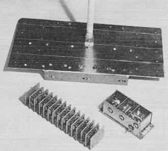
Stack of wafers is telemetry keying unit. while the three-chambered
unit is telemetry transmitter. End-panel antenna at back radiates telemetry signal.
When the satellite was tested and a launch date established with the help of the ARRL,
one question still remained. Could amateur tracking stations acquire and track the 100-milliwatt
OSCAR signal? On December 12, 1961, an Atlas-Agena rocket carried OSCAR I aloft, and
the friendly "HI" from orbit dispelled all doubts. Rare indeed was the OSCAR observer
who did not track OSCAR I from one horizon to the other with signals loud and clear.
Tracking reports continued to come into OSCAR headquarters even after the satellite
battery voltage had dropped to the point where the "HI" keyer had ceased to function.
At this point, it is estimated that the output power was approximately one milliwatt!
When a second ride into orbit became available, OSCAR II was launched on June 2, 1962.
It was identical to OSCAR I except for minor improvements such as the addition of more
batteries.
The Verdict: Success. These first OSCAR operations were unqualified successes. Nearly
1000 stations in 27 countries submitted some 10,000 tracking reports to OSCAR headquarters,
ranging from simple reception reports to comprehensive and highly competent technical
reports. Considering the limited resources of most of these amateur stations, the quality
of the reports was remarkable.
What was achieved? Much practical experience was gained which could not have been
obtained in any other way. Many participants designed complete tracking stations, built
and operated them, and wrote down their observations. Others became skilled at generating
orbit predictions from a minimum of information. Valuable data was collected on propagation
in the 2-meter band at orbital altitudes, as well as on the performance of space communications
hardware.
This amateur satellite activity also had international effects. The International
Telecommunications Union designated 144 to 146 mc. as an International Amateur Radio
Space Communications Band, thus providing radio amateurs all over the world with their
own window in the sky.
On to OSCAR III
The third OSCAR satellite will be capable of relaying
signals to ranges not normally possible in the 2-meter ham band. It contains a translator,
a telemetry system, and a coherent beacon transmitter, all using transistors. OSCAR III
is about the size of a small suitcase, 7" x 12" X 17", and weighs about 30 pounds.

Ed Hilton, W6VKP (left), and Don Norgaard, W6VMH, at work on the OSCAR
III package in Hilton's garage. In addition to designing much of the satellite electronics,
they also designed equipment for testing the units.
The translator is not a repeater in the sense of a receiver and transmitter connected
together, as there is no demodulation of received signals within the satellite. Signals
received at 144.1 mc. are converted to 30 mc. for amplification, and then reconverted
to 145.9 mc, for further amplification and retransmission. Figure 1 shows the functions
within the translator.
The translator will retransmit a single signal with a power of one watt. However,
if two or more signals are in the translator pass-band simultaneously, they will share
the watt in proportion to their strengths at the translator input. When no signals are
present in the pass-band, the output is noise only, due to the 130 dB system gain.
The telemetry system in OSCAR III (see Fig. 2) has three channels monitoring the main
battery voltage, the average internal temperature (which is the main battery temperature
since it is the largest thermal mass), and the highest internal temperature (the case
temperature of the translator output amplifier transistors). The telemetry system transmits
"HI" as an identifier, and the battery voltage channel is obtained by varying the rate
at which "HI" is sent. The other two channels are interspersed between "HI's" in bursts
of pulse-width telemetry modulation.
The coherent beacon transmitter (Fig. 2) is very close to the original OSCAR concept.
Its output is unmodulated, but its power is somewhat less than that of the OSCAR I and
II transmitters.

Fig. 1. As shown in this block diagram, the OSCAR III translator receives
signals at 144.1 mc., converts them to the 30-mc. i.f. frequency, then to 145.9 mc. for
retransmission. The satellite, which will relay signals in excess of 2000 miles, can
handle amateur AM, c.w., NBFM, RTTY and slow-scan TV signals.

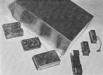
Shown here are the electronic components of OSCAR III grouped around
the case. Small unit at the extreme right is the low-power coherent beacon unit.

Fig. 2. Block diagrams detail functioning of telemetry (which transmits
"HI" as an identifier), coherent beacon for making Doppler shift measurements.
Four quarter-wave antennas are mounted on the sides of the OSCAR III package, one
for the translator input and one for the output, one for the telemetry transmitter, and
one for the coherent beacon. These antennas are made from a steel tape measure, and are
silver-plated. During launch, they will fold against the OSCAR III package, but when
OSCAR III separates from the launch vehicle to go its own way in orbit, each antenna
will snap erect.
The satellite package is made of magnesium-lithium alloy, the lightest commercially
available material obtainable, and covered with shiny aluminum foil tape to reflect the
heat of the sun. Black stripes are painted over the shiny aluminum to radiate heat away
from the package while it is in the shadow of the earth.
Power to operate the satellite is obtained from a large 18-volt battery. When it is
exhausted, the coherent beacon will begin to operate on power supplied by solar cells
(see Fig. 2) and a rechargeable battery.
Performance of OSCAR III
This, then, is OSCAR III. What can be done with it once
it is in orbit? As a communications relay satellite it should be able to relay signals
in excess of 2000 miles. This estimate is based on observations of the OSCAR I and OSCAR
II satellites. The translator will relay amateur AM, c.w., NBFM, RTTY, and slow-scan
TV signals equally well, and, because of this versatility, OSCAR III has been called
an amateur Telstar.
Besides its use as an orbiting relay station, many experiments can be performed with
OSCAR III. They can be divided into three categories - those requiring only a 2-meter
receiver and antenna, those requiring some test equipment in addition, and those requiring
an amateur radio operator's license.
Experiments in the first category can easily be performed by any SWL with a 2-meter
receiver. These experiments are to determine how long the satellite can be received on
a given orbital pass, to determine the battery voltage by measuring the time necessary
to send "HI" ten times, to write down any satellite-repeated amateur call-signs heard
for later identification, and to monitor the satellite frequencies when no signals are
expected in order to discover any unexpected propagation phenomena. These amateur satellite
experiments open up a whole new field for SWL's; reports could be of real value here.
The second experiment category requires an oscilloscope, a tape recorder, and a calibrated
audio oscillator. The experiments include obtaining data from the two temperature telemetry
channels, measuring Doppler shift, tape-recording slow-scan TV, high-speed RTTY or c.w.
signals, and making range measurements.
The third category of experiments requires a General Class amateur radio operator's
license. A few of the many possible experiments here are establishing scheduled communications
using the predictable reappearance of the satellite, making active range measurements,
and originating specialized communications signals, such as slow-scan TV, high-speed
RTTY, or high-speed c.w.
Future OSCAR's
Future OSCAR operations will depend somewhat on the results obtained
from OSCAR III, and on the degree of participation. Many ideas are currently being discussed
for possible inclusion in future satellites, such as a wider pass-band, more telemetry
channels, operation on other bands, and the use of solar cells to increase satellite
life.
More advanced ideas include communication between two satellites to increase the range
of relayed signals, an ionospheric penetration sounder operating in the 80-meter ham
band, and some means for detecting whistlers, naturally-occurring very-low-frequency
signals that are not completely understood.
Whether you intend to take an active part in one of the experiments outlined in the
preceding paragraphs, or just listen, a report of your observations would be appreciated.
Project OSCAR headquarters is located at Foothill College, Los Altos Hills, Calif. The
Project OSCAR program is the only space effort in which direct participation by amateur
and many professional scientists, both here and abroad, will be possible for some time
to come. We hope you will make use of it.
|


