|
|||||||||||||
 |
|||||||||||||
RCA's Numitron Readout |
|||||||||||||
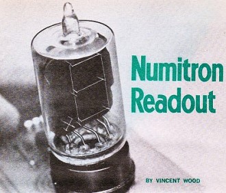
RCA's Numitron was their answer to the Nixie tube (manufactured by Burroughs Corporation). It was a simpler 7-segment incandescent display (DR2010) that, with all lines energized, formed the number 8. It worked off of +3.5 to +5 volts, with each element requiring 24 mA of current. The number 8 drew 192 mA of current and dissipated 0.672 W at 3.5 volts and a whopping 0.96 W at 5 volts! RCA marketed a BCD*-to-7-segment display driver (the CD2501E). The Numitron was pitched as a sensible alternative to the 7-segment LED display, but with an element size of 0.35" wide by 0.6" high, there was no real advantage over the LEDs, which were just entering the electronics market in 1970. Numitrons do have a certain nostalgic 'cool' factor, though. It is interesting to note that the author's last name, Wood, is the same as that of Frank Wood, who was issued the first U.S. patent for a 7-segment numerical display in 1910. * binary-coded-decimal Numitron Readout By Vincent Wood
Simplified Seven-Segment Display in One Tube There are many ways of displaying digital information. As readers of Popular Electronics are aware, digital readout can be achieved with ten small incandescent lamps; with a Nixie® glow tube, or with an incandescent-lamp, seven-segment display.* Each of these readouts is unique and has its own merits - and their use has made it possible for the electronics experimenter to build relatively low-cost digital systems. Now RCA has developed a new type of seven-segment readout that is so simple that your editors wonder why no one thought of it before. Basically, a seven-segment readout consists of seven narrow illuminated bars arranged to form a rectangular figure 8. As the associated logic circuits determine the numerical value to be displayed, the appropriate bars are illuminated to form the numeral on the display plane. The RCA approach to a seven-segment readout (called a Numitron) uses seven short filament wires to form the numerals, The filaments are suitably supported against a dark background and encased in a conventional 9-pin miniature tube glass envelope. As power is applied to the various filaments, they glow to form the appropriate numerals, Operating at voltages between 3.5 and 5 volts and requiring 24 milliamperes per segment, the Numitron has an expected operating life in excess of 100,000 hours. Since the segments are voltage operated, segment voltage may be varied to control the display brightness. Also, since the segments glow white, any color filter can be used in front of the display to get the desired result.
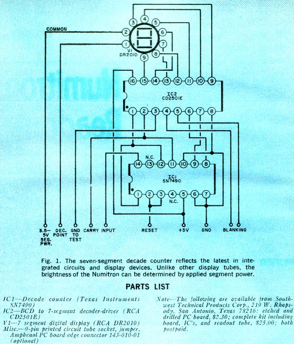
Fig. 1 - The seven-segment decade counter reflects the latest in integrated circuits and display devices. Unlike other display tubes, the brightness of the Numitron can be determined by applied segment power.
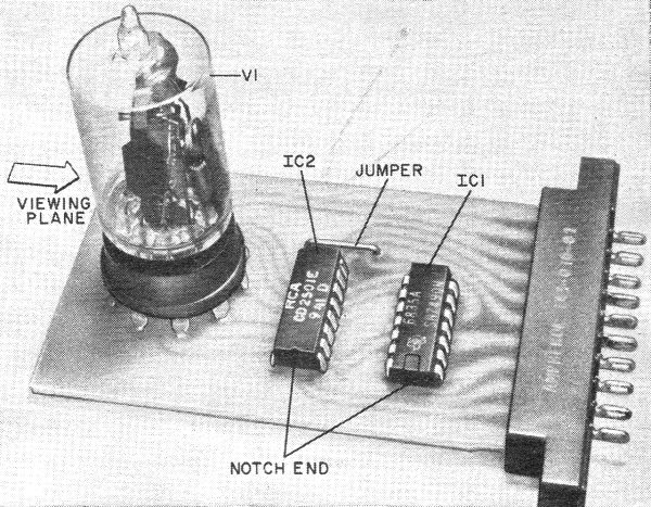
Fig. 3 - Component installation is simple as long as you observe the notch code on the IC's. The connector is optional.
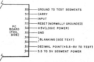
Fig. 4 - Power and signal connections for each decoder. Segments should be tested before each use. To accompany the Numitron, RCA has also developed a decoder-driver integrated circuit. Although the Numitron can be driven with the seven-segment board described in our February 1969 issue ("Third-Generation DCU", p. 43) , a much smaller and simpler PC board can be made using the new RCA CD 2501E IC. To further simplify the board and reduce the size, a Texas Instruments IC (SN7490) can be used as the decade counter to decode the incoming pulses. The circuit for the decade counter and display is shown in Fig. 1. Construction. To take full advantage of the small-size IC's and to avoid any possible wiring error, the readout should be constructed on a printed circuit board. A foil pattern for a board is shown in Fig. 2; you can make your own or purchase one already etched and drilled. Install the components as shown in Fig. 3. A conventional 9-pin printed circuit tube socket is used for the Numitron, V1. Be sure to observe the correct terminal placement on the IC's.
Fig. 2. Actual size printed circuit foil pattern for the readout. Connections to the board may be made by soldering directly to the foil terminations or through a conventional 10-pin Amphenol PC board edge connector. Testing and Operation. Once this board is complete, make external connections for testing as shown in Fig. 4. The 5-volt d.c. line, which can be used for both logic and segment power, should be capable of delivering about five hundred milliamperes. With the two 5-volt supplies and the ground terminal connected, connect the "ground to test segments." All seven segments should light. This test insures that all segments are operating and should be performed each time the readout is used to make sure of correct display. For example, if the center segment is not operating, all 8's appear to be zero's. To test the decimal point, connect the "decimal point" terminal to the 5-volt source. Pushbuttons may be used to perform these two functions. The CD2501E integrated circuit also has an optional blanking circuit. The board terminal that connects to pin 5 of IC2 is grounded in the readout associated with the most significant digit of a multi-readout display. The connection to IC2 pin 4 is then connected to the preceding board at IC2 pin 5, and so on down the line. These connections permit the IC to blank the associated display if the input to that readout is a zero. Thus, if six readouts are used in a circuit, and only the first three digits are required, the unused displays would be dark rather than displaying a series of three zeros which may add confusion. With the reset lead grounded, apply an input signal of about 2 volts to the board terminal marked input in Fig. 4. The signal from an audio generator may be used. As the low-frequency audio signal is applied, the display will start to indicate. To reset to zero, lift the "reset" terminal from ground and apply +5 volts d.c. *See the following Popular Electronics articles: "Build a Low-Cost Counting Unit," p 27, February 1968; "All-Purpose Nixie® Readout," p 67, November 1968; "Third-Generation DCU." p 43, February 1969.
Posted March 3, 2021 |
|||||||||||||
 |
|||||||||||||
|
|||||||||||||


|
||||||||||||||||||||||||||||||||||||


