|
|||||||||||||
 |
|||||||||||||
Instrumenting an Earth Satellite
|
|||||||||||||
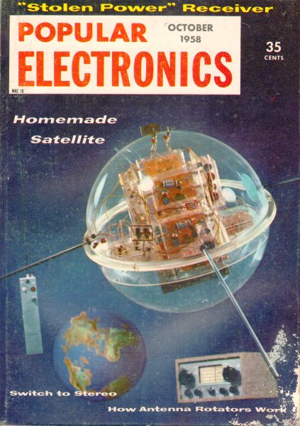
In October of 1958 when this Popular Electronics magazine article was written, a mere year had passed since the successful launch of Sputnik and a few months later the launch of the Explorer satellite - the first ever for Russia and the USA, respectively. Prior to that time all satellites were cosmic conglomerations of rock, metal, and/or gas. There were no manmade satellites except for a couple remnants of test rockets that happened to reach orbital heights. That Ronald Michael Benrey, a highschooler of the day, would design and enter an "Earth Satellite" to demonstrate some of the technology needed to an actual orbiting satellite was a phenom. Most people hadn't even learned to spell "satellite" yet, and did not commonly refer to planets, moons, and asteroids as satellites. His creation took second place in the National Science Fair and first prize in the USAF's Awards Program. Instrumenting an Earth Satellite  By Mike Bienstock By Mike BienstockAssociate Editor Ar'gus (är'gus), n. | L., fr. Gr. Argos. | 1. Gr. Myth. A hundred-eyed monster set to watch Io. 2. A watchful guardian. Webster's definition of Argus is incomplete. In Greek mythology, Argus has another connotation - it denotes the starry heavens. In all respects, it is a fitting name for a model satellite - "Argus I" - built by Ronald Michael Benrey and entered in the National Science Fair. The satellite took second prize at the Fair and took first prize in the Air Force's Awards Program, as well as receiving other citations. While it doesn't have the 100 eyes of the mythological Argus, it does have seven "eyes" - sensors designed to "see" such things as temperature, ultraviolet light, and micrometeorites-as well as two "voices" - transmitters to relay the information to receivers.
A view of the "works" in Argus I. Note that almost all components are cased in plastic to allow full visibility - the metal box at bottom houses the "Brain".
The designer of the satellite is shown at making an adjustment in an equatorial thermistor sensor which registers skin temperature.
Diagram shows frequencies used by satellite.
Interior of satellite looks like this from the top. Equipment is mounted on circular sheet of Plexiglas which rests against lower hemisphere. The satellite shell is made of Plexiglas, 18" in diameter, in two hemispheres. Most of the components are mounted in plastic boxes within, for visibility. With the antennas in place, "Argus I" measures 54" in diameter and weighs 20 pounds. With batteries, it weighs 30 pounds. It is completely transistorized, using 15 transistors in all. Total cost of the project was about $200. Ground Control When set up, the ground control equipment consists of a modified radio control transmitter operating on 27.255 mc. and three receivers, one tuned to the constant frequency of satellite transmitter Number I (820 kc.,) and the other two to the frequencies of transmitter Number II (1220 and 1300 kc.). To conserve battery power, one of the satellite's transmitters is silent until keyed by the ground transmitter. The satellite carries a two-transistor receiver to pick up the R/C ground interrogation signal, automatically keying the "Brain" into its instrumentation cycle. Telemetering System If "Argus I" were put into orbit, it would telemeter the following information back to earth:
The basic circuit in the telemetering system is shown in the schematic. The pulse rate of the unit (a metronome, in effect) is varied by using a resistance changing sensor in place of a variable resistor. Such sensors include a thermistor for temperature, photocell for ultraviolet rays, and erosion gauge for micrometeorites. The erosion gauge is a mirror with the paint backing carefully removed with a cotton pad dipped in nail polish remover, or it can be a photocell with an opaque coating. In the case of the former, the "sandblasting effect" of micrometeorites erodes some of the silver from the back of the mirror, changing the resistance; in the case of the latter, the erosion allows more light to get through to the cell. In this way the sensor-pulser unit's pulse rate is a function of the phenomenon measured. Instrumentation Cycle The output of these units is amplified and each pulse keys the transmitter via a keying relay. Each pulser is turned on, hooked to the proper sensors and connected to the transmitter by the "Brain." This consists of a "timed" 22-position five-deck stepping relay which advances one position every five seconds, giving "Argus I" a programmed instrumentation cycle. By "turning off" the Brain timer by means of radio control, the cycle can be stopped at any point for prolonged observation of one physical phenomenon. You Can Record the Satellites You can join in the greatest of all science experiments - the scouting of space by the IGY satellites. A new Audio Devices booklet describes how to use a modified FM broadcast receiver in conjunction with a stable communications receiver to tune in the signals from the satellites. With your tape recorder, you can record the latest "news" from the heavens about meteors, ultraviolet radiation, and other space phenomena. This booklet not only tells you how to make and interpret the satellite recordings but, most important, it explains how you can determine if your recordings have value to the official satellite project. For your copy of "You Can Record the Satellites," see your audio dealer or send 10 cents to Audio Devices, Dept. PE-10, 444 Madison Ave., New York 22, N. Y. A second transmitter is included to allow the listener to know when the instrumentation cycle is starting and when the Brain is advancing. Both transmitters are one-transistor c.w. oscillators with a power in-put of 15 mw., and are fed by a 15-volt hearing aid battery. A separate ultraviolet photocell changes the capacitance of the tuned circuit of transmitter Number II. As this sensor alternately faces and turns from the sun, the frequency of the transmitter is changed, switching from 1220 to 1300 kc. The frequency difference is relatively large so that the natural Doppler shift doesn't affect the solar aspect indication. Sensitivity is low, so starlight, moonlight or earth glow doesn't affect the sensor. The radio control receiver in the satellite is tuned to a frequency of 27.255 mc., and is powered by two 1.5-volt penlight cells and a 22.5-volt battery. The transmitter, a typical radio control unit, has a 3.2- watt input.
Block diagram outlines functions of the model satellite. Pulses of the instrumentation cycle, varied by the sensors from five beats to one-half beat per second, sound like short, staccato "beeps" typical of the Sputniks.
Exhibit of Argus I which netted Ronald second prize at the National Science Fair. He is holding R/C transmitter used to query satellite.
Pulser circuit above feeds sensor information to transmitter, where it is sent in its proper sequence at a signal from the "Brain." Decoding Equipment needed to decode the cycle includes three receivers, Doppler effect correction devices, a graph-type recording counter with device for noting solar aspect, and interferometer (if desired). The beep rate is counted by the graph counter and notations are made by the operator regarding which phenomenon is being recorded. The number of beeps per time unit is then plotted against a prepared graph. The satellite's power supply consists of an NT6 (Willard) 6-volt storage cell for the Brain, and eight 15-volt hearing aid batteries in addition to the 22.5-volt battery and two 1.5-volt penlight cells. There is provision in the Brain for the use of cosmic ray detectors, and the versatility of the satellite is further enhanced by universal connections which allow change of instrumentation simply by Changing sensors. If "Argus I" were to be set in orbit, a vertical axis spin would be imparted by the last stage of the rocket. Chances are it will never see the undiluted light of space. However, in its earth trials, the satellite performs its mission perfectly. Perhaps it will serve as a prototype of things to come. The satellite's designer, lives in the Bronx, New York, and has just entered Massachusetts Institute of Technology. Ronald plans to major in physics and expects to go on and make his career in the field of electronics.
Posted August 31, 2022 |
|||||||||||||
 |
|||||||||||||
|
|||||||||||||


|
||||||||||||||||||||||||||||||||||||


