|
|||||||||||||
 |
|||||||||||||
Inexpensive Wheatstone Bridge
|
|||||||||||||
Before the ready availability of inexpensive, accurate multimeters, obtaining a highly precise measurement of resistance required something like a Wheatstone bridge. According to Wikipedia, "The Wheatstone bridge was invented by Samuel Hunter Christie in 1833 and improved and popularized by Sir Charles Wheatstone in 1843. One of the Wheatstone bridge's initial uses was for the purpose of soils analysis and comparison." This article from a 1972 issue of Popular Electronics magazine discusses the operation of the Wheatstone bridge and includes a construction project for anyone interested. 100 Milliohms to 10 Megohms with 0.5 % Accuracy By Robert P. West, Jr.
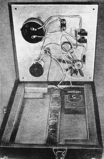
Fig. 1. The bridge can measure from 0.1 ohm to 10 megohms with 0.5% accuracy. When it comes to measuring resistances, the Wheatstone bridge is superior to any voltohmmeter (except for some very expensive electronic types); but few experimenters can afford even a resistance bridge. So they usually fall back on the always-available VOM. In today's circuits, such things as RC time constants (for instance) must be measured very accurately; and the precision of a voltage divider can make or break a circuit design. In such cases, the VOM can't always be counted on to do the proper job - primarily because of the readout system employed. You may be trying to read the resistance of a component that has an accuracy of 0.5% but as long as you have to interpolate the values on a meter scale, your efforts are in vain. The resistance bridge described here is simple to construct and, since most of the parts can be obtained from a surplus store, it shouldn't cost more than $15.00. What's more, it has an accuracy of 0.5% with a range of 100 milliohms to 10 megohms.
Short heavy leads reduce internal resistance. Note novel battery layout. Construction. The circuit, shown in Fig. 1, is wired point-to-point, with #18 connecting wire. (This size wire is necessary to avoid inaccuracies in the lowest range.) The bridge can be assembled in a wooden or metal box about 2 1/4" x 7" x 7" or larger. All components are mounted on the front panel except the 4 "D" cells, which are secured to the case by a holder, and the 67 1/2-volt battery which may be held by a clamp. Calibration. Set R1 to its maximum resistance and rotate selector switch S3 to the R7 (10,000-ohm) range. Connect a 10,000-ohm resistor between test jacks J1 and J2; depress test switch S1; and adjust calibration potentiometer R2 for a null (zero center) on meter M1. As the null is approached, depress meter sensitivity switch S2 to make the final adjustment. When this operation is complete, the total resistance of R2 and R3 is equal to that of R1. Remove the 10,000-ohm resistor from the test jacks. Once again depress the test switch and note which way the meter deflects. Mark that side of the meter with a plus sign and the other side with a minus. The bridge is now balanced and ready for use. Operation. To determine the value of an unknown resistance, connect the unknown across the test jacks. Always start with S4 in the Below 100K position. In the Above 100K position, a potential of 73.5 volts is placed across the bridge; and if the resistance being tested were of low value, or if the range selector were in the low range, destruction of one or both could result. Now depress test switch S1. If the meter indicates on the plus side, the unknown resistance is larger than R1. If R1 is already at the maximum value (10), switch to the next higher range on S3. Continue until the meter is in the minus range. Now rotate the calibrated dial of R1 until the meter approaches a null. While holding clown the test switch, depress sensitivity switch and adjust R1 for perfect null. After releasing the test and sensitivity switches, read the value of your unknown directly from the calibrated dial. For instance, if the dial reads 8.59 and the switch is on 10K, the unknown is 8.59K.
Although the prototype was built in a wood case, any type of construction may be used. Note the 10-turn dial. How It Works. Essentially, the resistance bridge is a ratio detecting network. When the value of R1 is in the same ratio to the unknown resistance as R2 + R3 is to the range select resistor (through S3), no current flows through the meter leg, producing a null on the meter. When the meter is nulled by adjusting R1, we are balancing the ratio of the corresponding resistance in the legs of the bridge. This ratio is mechanically coupled to the calibrated dial of R1 and direct readings are obtained. Actually, R1 could be any value of ten-turn potentiometer as long as R2 + R.3 is equal to it in resistance. The fact that most ten-turn pots, such as the one recommended in the Parts List, have 5% tolerance of the total value doesn't affect the bridge operation because of the built-in compensation with R2. What does concern us is the linearity of R1. In this case, it is 0.5%. The range select resistors remain the same. For example: if R1 were a 5000-ohm potentiometer; R2 + R3 must also be 5000 ohms. Then if the unknown resistor were 5000 ohms, the range selector would be in the 10K range. The ratio of R2 + R.3 to the range select is 2:1 and the meter would null when R1 was in a 2:1 ratio with the unknown. Then R1 must be 2500 ohms to null the meter and the resistance of R1 is one half of its full range. The dial would read 5.00. In this bridge, R1 was chosen to be 10,000 ohms because this value is not so low that it will allow high current to flow when a 10-megohm resistance is being checked. Nor is it so high that it causes inaccurate measurements in the low ranges.
Posted March 7, 2023 |
|||||||||||||
 |
|||||||||||||
|
|||||||||||||


|
||||||||||||||||||||||||||||||||||||


