|
|||||||||||||
 |
|||||||||||||
How to Align Receivers
|
|||||||||||||
Even in the year 2022, there are still plenty of receivers around that need to be manually aligned for peak performance. They are not necessarily all older equipment, either. Super sensitive receivers for radars, radio astronomy, and security systems are some examples, especially when a combination of center frequency and bandwidth adjustments are necessary. Of course there are plenty of amateur radio receivers and vintage AM, FM, and shortwave radios around that are still in service by hobbyists and collectors. Most of those people probably already know how to tune their radios, but there are always new enthusiasts just entering into the realm that need a helping hand. This article titled "How to Align Receivers" appearing in a 1954 issue of Popular Electronics magazine will be a big help to them. How to Align Receivers
Fig. 1 - Basic receiver adjustments (dotted boxes) that a layman can make. See text. Modern superheterodyne receivers have a number of tuned circuit adjustments which must be set properly if top performance is to be obtained. This is as true of small table model receivers as it-is of large AM-FM-short-wave consoles. The more complex sets simply have more adjustments and, where FM or TV is provided, may require slightly different techniques for adjustment. The entire adjustment procedure, whether applied to a table model receiver or a large console, is called receiver alignment. While the beginner should steer clear of FM and TV sets and the more complex consoles, there is no reason why he shouldn't undertake the alignment of table model AM broadcast-band receivers, if he has or can borrow the necessary test equipment - a multitester (not absolutely essential), an insulated alignment tool, and an r.f. signal generator. The basic adjustments made in a table model receiver during the alignment procedure are shown within the dotted line boxes in the Simplified diagram of Fig. 1. No attempt should be made to align a receiver unless it performs poorly and preliminary tests indicate that the set is out of alignment. Alignment is not a magic "cure-all" that will correct hum, noise, distortion, weak operation, and other complaints, irrespective of the actual cause. Many beginners make the mistake of trying to align sets to correct defects which they are unable to find because they lack the necessary training and experience. The fact is, the average receiver seldom requires realignment unless it has been mistreated. Here are the symptoms which may indicate the need for alignment: (1) If the set is weak, but all tubes test good and d.c. voltages in the receiver are normal (check these against the voltage values listed in the service manual for the receiver). (2) If the receiver does not "track" its dial (that is, if the dial readings do not correspond to the frequency or wavelength values for the station tuned in) but make sure that it isn't just a case of the dial pointer slipping. (3) If the receiver squeals or oscillates, but tubes are goad and all d.c. voltages seem normal, and bypass and filter capacitors are in good condition or, if the oscillation occurs only at one end of the band (generally the low frequency end).
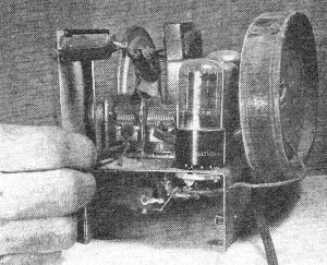
Fig. 2 - A typical set up for making receiver alignments as described in the article.
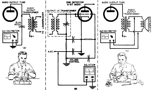
Fig. 3 - Three methods of connecting receiver and the test meter. (A) Meter connected through a capacitor. (B) With a v.t.v.m. (C) Meter connected across voice coil.
Fig. 4 - How a multitester can be connected across the loudspeaker voice coil terminals.
Fig. 5 - Receiver adjustment points on top of the chassis. See text for full details.
Fig. 6 - Two types of radio tuning capacitors. The one on the left is found in broadcast-only receivers while the one on the right will be more often encountered in combination short-wave and broadcast type sets.
Fig. 7 - Adjusting the local oscillator trimmer. Above all, take care not to confuse other tuning circuit troubles with the need for alignment. For example, a common complaint is that the receiver picks up one station over the entire tuning range. This is not generally due to misalignment; rather, it is usually the result of a defective local oscillator, The operation of a local oscillator may be checked by using a d.c. voltmeter to check for d.c. voltage across the oscillator grid resistor (identify the grid pin connection by referring to a tube manual). If there is a reasonable d.c. voltage here, generally 5 volts or more, the oscillator is probably OK. If not, check plate and screen grid voltages in this stage and, if these are normal, try a replacement tube, no matter how the original tube checks in a tube tester. Make sure the oscillator section of the tuning capacitor is not shorted (we'll discuss the identification of this section later) and, as a final step, replace the oscillator coil. For alignment work you'll need an r.f. signal generator and an insulated alignment tool, In addition, you'll need an output indicator of same sort. A d.c. vacuum-tube voltmeter is the preferred instrument for this job, but you can get by with an ordinary multitester, or, in a pinch, by using the loudspeaker of the set as an output indicator. A typical set-up for receiver alignment is shown in Fig. 2. The output meter may be connected to the receiver in one of several ways. Three good methods are shown in Fig. 3. If a d.c. vacuum-tube voltmeter is available, connect its common lead to chassis ground and the negative d.c. lead to measure receiver a.v.c. (automatic volume control) voltage, as shown in Fig. 3B. In many sets". this connection will be to the "hot" side of the volume control. If a multitester is to be used as an output indicator, set it up for use as an a.c. voltmeter. The meter may be connected between chassis ground and the plate pin of the audio output tube through a .5 μfd., 600 volt capacitor, as shown in Fig. 3A. If preferred, the meter may be connected directly across the loudspeaker voice coil terminals, as shown in Fig. 3C. A typical connection is shown in Fig. 4. If the loudspeaker is to be used as an output indicator, you'll listen for changes in the loudness of a tone. The outer shield of the signal generator lead should be connected to chassis ground and the "hot" center lead should be connected through a .001 μfd. paper capacitor (600 volt) to the control grid terminal of the mixer tube for i.f. transformer alignment. (Identify the proper pin connection by using a tube manual. Typical mixer tubes are the 6K8, 6A8, 6A7, 6SA7, 6BE6, 12SA7, 12BE6, etc.) For "front end" alignment, the hot lead of the signal generator may be simply clipped to the loop antenna, as shown in Fig. 2. No direct electrical connection is made to the set. Finally, plug in the test equipment and the receiver, turn on all units, and allow a few minutes warm-up time before starting alignment. The i.f. transformers are generally located in rectangular metal cans on top of the receiver chassis, as shown in Fig. 5. Two adjustments are usually provided in each transformer. These may both be on the top or .sides of the can, or one may be on the top and the other on the bottom (below chassis). Most modern receivers use a two-gang tuning capacitor. Either of the two types own in Fig. 6 may be used. Trimmer capacitors for the two sections are frequently mounted on one side of the stator plates (the stationary plates ... the movable plate section is called the rotor), but, in some cases, these adjustments may be on the bottom of the tuning capacitor frame. If the tuning capacitor is like the one shown to the left, the smaller rotor plates belong to the local oscillator section. If the capacitor is like the one shown to the right, you'll have to identify the oscillator and r.f. sections before alignment.If you are able to pick up a station with the receiver, bring one finger close to one set of stator plates, then close to the second set. As you approach the r.f. stator section, you may find that the signal becomes weaker, but will not disappear; as you bring your finger close to the oscillator section, however, the station may disappear entirely, and you may even find that a different station is picked up. Should the receiver be so far out of alignment that it is impossible to tune in a station, you can identify the oscillator section either by tracing out the circuit or by referring to a service manual. Referring back to Fig. 1, the i.f. transformer adjustments correspond to trimmer capacitors C6, C7, C8, and C9. In some receiv-ers, i.f. tuning "slugs" (movable iron cores) may be used instead of trimmer capacitors. This is usually the case where adjustments are provided on both the top and the bottom of the i.f, can. The r.f. trimmer capacitor (on the side of the tuning capacitor) corresponds to C3 while the local oscillator trimmer capacitor corresponds to C4. In many receivers, a low-frequency adjustment for the local oscillator will be provided. This may be either an adjustable local oscillator coil, using a movable powdered iron core, or a small "padder" in series with the tuning capacitor (C5 in Fig. 1). Where especially cut plates are employed on the tuning capacitor, like the one shown to the left in Fig. 6, the chances are that no low-frequency adjustment is provided. In any case, if a low-frequency adjustment is available, you should be able to identify it by checking the connections to the oscillator coil. With the signal generator connected to the grid of the mixer tube, as previously outlined, set the instrument controls to deliver a modulated r.f. signal at the i.f. value for the set. For most receivers this will be either 455 or 456 kc. Set the output level controls (the coarse and fine attenuators) to the minimum signal required to obtain an indication on the output meter used (or so that a faint tone can be heard in the loudspeaker, the receiver volume control should be turned up full. Turn the tuning control of the receiver until the tuning capacitor plates are full meshed. Short out the local oscillator temporarily. Do this by connecting a short piece of wire between the lug for the stator plates of the local oscillator section of the tuning capacitor and ground. Now, using an insulated screwdriver or alignment tool, adjust the i.f, transformers for maximum output indication on the output meter (or maximum sound from the loudspeaker). The proper technique to use is shown in Fig 5. The output meter and signal generator are not shown in this photo. Go through the adjustment steps at least twice, for the setting of one i.f. transformer may affect the adjustment of the other. The mixer stage and local oscillator are generally called the "front end" of the receiver. This section is aligned after the i.f. transformers are properly adjusted. With the outer shield of the signal generator lead still connected to chassis ground, remove the .001 µfd. capacitor used when adjusting the i.f. transformers, and clip the "hot" lead to the loop antenna of the receiver, as shown in Fig. 2. A direct electrical connection is not usually necessary. Remove the temporary shorting wire used on the local oscillator in the previous steps. Next, set the signal generator to 1550 or 1600 kc. and tune the receiver to the same frequency, as indicated by the dial setting. Adjust the local oscillator trimmer (C4 in Fig. 1) for maximum output. The proper technique to use is shown in Fig. 7. Shift the signal generator and the receiver tuning to 1400 kc. and adjust the r.f. trimmer (C3 in Fig. 1) for maximum output. Finally, if a "padder" (C5 in Fig. 1) or an adjustable local oscillator coil is provided in the receiver, tune both the signal generator and the receiver to 600 kc. Make the low-frequency adjustment (coil or padder) for maximum output while rocking the tuning capacitor plates back and forth (by adjusting the tuning knob). Use the adjustment and dial setting that gives maximum output, irrespective of the actual reading of the receiver dial. Finally, go back to the high-frequency settings of the signal generator and receiver and repeat the adjustments of the local oscillator and r.f. trimmers. You may then wish to repeat the adjustment at the low-frequency end of the dial, for, if best receiver performance is to be obtained, the alignment procedure should be carried out as a back-and-forth process. One adjustment affects the other, so you have to make slight changes in both to get the best possible setting of all trimmers. END
Posted October 24, 2022 |
|||||||||||||
 |
|||||||||||||
|
|||||||||||||


|
||||||||||||||||||||||||||||||||||||


