|
August 1956 Popular Electronics
 Table of Contents Table of Contents
Wax nostalgic about and learn from the history of early electronics. See articles
from
Popular Electronics,
published October 1954 - April 1985. All copyrights are hereby acknowledged.
|
As with nearly things electronic, innovations in radar systems that were ground-breaking
a few decades ago are now available commercially at a small fraction of the cost,
a much more compact size, and much greater performance and reliability (see Furuno
at right). Radar operators during World War II noticed that they were able
to detect strong rainstorms demonstrating that signals did not necessarily need
a metallic object to be reflected strongly enough to be received and processed.
Research began soon thereafter to build radars optimized for detecting weather phenomena.
Early weather radars were "simple" reflective types that indicated distance, height,
and speed (by comparing successive samples). Doppler radar was developed next, adding
a much greater capability to characterize particular weather systems according to
intensity, direction, rotation (hurricanes , tornadoes), composition (ice, snow,
rain, etc.), speed (average and gust), and other parameters.
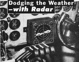
Dodging the Weather - With Radar

Radar indicator installed in cockpit of Delta airliner tells
pilot at a glance the kind of cloud formation he is heading for. Analyzing the radar
pattern, he can steer the plane dear of turbulent areas, avoiding risks and bumpy
ride.

Compact cockpit control features special adjustment to gage cloud
density, turbulence and force of precipitation.

Top: Indicator shows plane flying toward a weather front approximately 10 miles
ahead. Rings indicate distance.
Center: Aircraft is approaching "soft" spot with rain centers (showing black)
about seven to ten miles out on each side.
Bottom: Plane is now cutting through minimum turbulence area with clear sky straight
ahead.
Radar picks safe spots amid stormy skies.
Heading for the clouds can be tricky business if you haven't got your feet on
the ground. In fact, unexpected weather fronts constitute one of the main hazards
of flight.
Collins Radio Company has recently developed an airborne weather radar system
that provides immediate indication of the weather ahead. The information is displayed
in the form of a weather map showing conditions within a radius of 150 miles and
approximately 240 degrees around the nose of the, aircraft. This map-like image
on the radar screen shows the location of weather fronts in terms of range and azimuth
bearing relative to the position of the aircraft. It identifies areas potentially
dangerous to flight, such as thunderheads, hailstorms, or turbulent areas associated
with heavy rainfall. With this map as a guide, pilots can investigate aircraft to
avoid storms or turbulent areas, usually by detours of five miles or less from the
planned flight path.
The weather map is created by the reflection of high-frequency radar waves from
rain, hail, snow and ice. When these elements are not present in a cloud structure,
energy is not reflected and hence no warning weather map is displayed on the cockpit
indicator. Such "empty" clouds can be traversed with little or no difficulty.
To allow aircraft to be piloted safely through thunderstorms, information regarding
turbulence, rain, snow and icing conditions must be obtained. Such information is
based upon rainfall gradients (i.e., varying rainfall densities at different distances)
which can be displayed on the radar screen by a unique circuit.
These rainfall gradients are pictured by insertion of a so-called "iso-echo"
circuit, which shows areas of heavy rainfall as dark areas - or black holes within
the brighter image of areas with only light precipitation. In this way it is possible
for the pilot to spot the more dangerous areas within the cloud formations themselves.
Turbulence is recorded indirectly. Varying degrees of turbulence exist in the
areas of heavy rainfall. While turbulence itself cannot be seen on a weather map,
it is known to be greatest where the rainfall gradient is highest, i.e., where the
pattern is dark. The system may also be used to provide a ground map which gives
a visual display of cities, rivers, lakes, shorelines, mountains and other terrain
conformations. This ground map serves as an invaluable navigation aid, effectively
extending the vision of the pilot during all conditions which restrict visibility.
To enhance reliability, magnetic amplifiers and mineral diodes are used wherever
practical since these components have no filaments and thus avoid the possibility
of filament failure. In addition, this assures an efficient system with low heat
dissipation, low current drain and power demand.
The system can be used with two indicators operating simultaneously. This arrangement
offers the advantage that each indicator can be set to a different range, so that
both nearby and distant conditions are depicted simultaneously.
Printed wiring is used to provide physical strength and to insure precise placement
of components and proper length of leads. Delta Airlines, the first to use this
installation, has thereby added another safety factor as well as passenger comfort
to its flights.
 
Radome nose, made of special plastic transparent to microwave
radiation with only minimum power loss, is bolted onto the fuselage of Delta airliner
housing the first commercial Collins Airborne Weather Radar. With radome removed,
you can see antenna at right.
|


