|
|
|||||||||
| Software: RF Cascade Workbook | RF Symbols for Office | RF Symbols & Stencils for Visio | Espresso Workbook | ||||||||||
|
|||||||||||||||||||||||||||||||
   |
   |
||||||||||||||||||||||||||||||
|
Please Support RF Cafe by purchasing my ridiculously low-priced products, all of which I created. RF & Electronics Symbols for Visio RF & Electronics Symbols for Office RF & Electronics Stencils for Visio T-Shirts, Mugs, Cups, Ball Caps, Mouse Pads These Are Available for Free |
|||||||||||||||||||||||||||||||


Popular Electronics Builds a Vacuum-Tube Voltmeter - the VoltOhmyst
May 1959 Popular Electronics
May 1959 Popular Electronics  Table of Contents Table of Contents
Wax nostalgic about and learn from the history of early electronics. See articles from Popular Electronics, published October 1954 - April 1985. All copyrights are hereby acknowledged. |
RF Cafe visitor Terry W. wrote to me about a topic that ended up mentioning RCA's vacuum tube voltmeter (VTVM) known as the VoltOhmyst. VTVMs were the era's high-input-impedance multimeter, before field effect transistors (FETs) came on the scene. The higher a meter's input impedance, the less it loads the circuit under test. Any meter connected across a circuit appears as a parallel load to the source, so the closer it is to an open circuit, the better. Terry mentioned how the VoltOhmyst was a key component on test benches of many professionals. You can still buy various models of the VoltOhmyst on eBay. This 1959 Popular Electronics magazine article reports on the kit version which at the time used vacuum tubes. Later models sold into the 1970s were solid state. The printed circuit board in the 1959 model was very avant-garde in a time when point-to-point was still the norm.
Popular Electronics Builds a Vacuum-Tube Voltmeter

Printed-circuit board makes the RCA VoltOhmyst an easy-to-assemble kit.
 The first piece of quality electric test equipment
you should have for your test bench is a vacuum-tube voltmeter. A VTVM found in
service shops and industrial plants throughout the country, the RCA "VoltOhmyst,"
Type WV-77EK, is now being offered in kit form.*
The first piece of quality electric test equipment
you should have for your test bench is a vacuum-tube voltmeter. A VTVM found in
service shops and industrial plants throughout the country, the RCA "VoltOhmyst,"
Type WV-77EK, is now being offered in kit form.*
What It Can Do. The VoltOhmyst WV-77EK measures a.c. (r.m.s.) and d.c. voltages up to 1500 volts, peak-to-peak voltages to 4000 volts, and resistance up to 1000 megohms. There is a high input impedance on all d.c. and a.c. voltage ranges, allowing the use of this VTVM in circuits where VOM's with a lower input impedance would result in loading of the circuit under test - and a resultant error in voltage reading.
The VoltOhmyst utilizes a push-pull balanced d.c. bridge with the meter in the plate circuit, which affords excellent linearity of response, good stability, and very high input impedance. Additional features include: provision for zero-center indication, useful in discriminator and bias measurements; separate scales for low a.c. voltage measurements to assure accurate readings; a circuit design which allows measurement of a.c. in the presence of d.c. and vice versa; a separate d.c. probe with a 1-megohm resistor which minimizes capacitance-loading effects; and electronic protection against meter burn-out. Also, the resistors in the ohmmeter ranges are protected by a separate fuse.

Large, clear meter face permits quick, accurate readings.

Completely wired unit. Note the three internal adjustment potentiometers. Diagram below is from the construction sheet.

Well planned illustrations reduce complex wiring to a simple task.
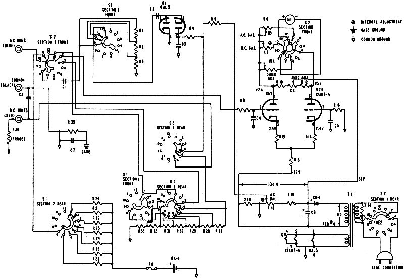
The VoltOhmyst uses a time-proven RCA circuit for optimum results.
* For complete information on the VoltOhmyst, write to Radio Corporation of America, Commercial Engineering Dept., Section PE-10, Harrison, N. J.
Putting It Together. The WV-77EK utilizes a printed-circuit board to facilitate assembly. This board provides a rugged, pre-wired mounting for the components and, if the parts are properly inserted and soldered, makes for a neat and trouble-free assembly.
The symbol number of the part to be mounted is printed on one side of the board, and the copper wiring is etched on the other side. When the assembly instructions call for mounting a part, make sure the leads of the component form a right angle to the body of the part. The leads, when properly bent, form the two long portions of a "U" shaped unit, the bottom of the "U" matching the dimension between the two holes. Some parts, such as the disc capacitors, tube sockets and the selenium rectifier, do not require bending.
Place the leads in the holes provided and pull the part snug to the board, so that the leads protrude on the etched side of the board. Spread the leads slightly to prevent the part from falling out. After soldering the leads to the copper foil, cut them to 1/8" from the board.
Recommendations. The instructions for assembling and wiring the VoltOhmyst have been carefully thought out and presented in seven major construction steps. The POPULAR ELECTRONICS editor who assembled the VoltOhmyst makes the following recommendations.
- Insert R14 as the first substep in Step 2. This section of the printed circuit is crowded. Installing R14 first will permit you to mount the adjoining components with ease.
- After mounting the two snap-in sockets on the printed-circuit board as instructed in Step 2, be sure to solder each connection point as instructed. Do not be fooled into thinking that these connection points make a good electrical connection.
- When connecting R10 to the printed-circuit board in Step 4, do not cut the leads. Otherwise, wire must be added to reach a connection point later on.
- In Step 4, the instructions call for tinning the negative and positive terminals of the dry cell. When doing this, be careful not to apply too much heat with the soldering iron. Excessive heat will damage the cell.
In general, the calibration procedure permits satisfactory calibration for most servicing purposes.
Comment. The VoltOhmyst assembles without difficulty, works nicely, is fairly rugged, and has ample accuracy for most practical work. The meter face is large, calibrations are fairly easy to read, and the knife-edge pointer permits readings with good accuracy. This reliable measuring device will prove extremely useful in television and hi-fi repair as well as in many industrial applications.
Posted September 28, 2021
(updated from original post on 2/20/2013)

Copyright: 1996 - 2026 |
About RF Cafe RF Cafe began life in 1996 as "RF Tools" in an AOL screen name web space totaling 2 MB. Its primary purpose was to provide me with ready access to commonly needed formulas and reference material while performing my work as an RF system and circuit design engineer. The World Wide Web (Internet) was largely an unknown entity at the time and bandwidth was a scarce commodity. Dial-up modems blazed along at 14.4 kbps while tying up your telephone line, and a lady's voice announced "You've Got Mail" when a new message arrived... |
Copyright 1996 - 2026 All trademarks, copyrights, patents, and other rights of ownership to images
and text used on the RF Cafe website are hereby acknowledge My Hobby Website: My Daughter's Website: |
