|
December 1971 Popular Electronics
 Table of Contents Table of Contents
Wax nostalgic about and learn from the history of early electronics. See articles
from
Popular Electronics,
published October 1954 - April 1985. All copyrights are hereby acknowledged.
|
 Steerable phased array antenna systems used
to be the exclusive domain of military and aerospace radar and electronics warfare
systems. The expense involved in both the hardware (structure, antenna elements,
electric power, cooling) and the electronics required for controlling the beam was
expensive and complicated. Larger phased array antennas for lower frequency (longer
wavelength) bands are still relatively expensive. However, small cell wireless phone
and WiFi applications in the 2.4 GHz and higher bands are seeing the development
and deployment of phased arrays that will search for and track individual users
in order to allocate antenna gain and signal power where it is needed, rather than
using an omnidirectional radiation pattern. Physically steered directional antennas
are not capable of the speeds needed to do the job. In the last couple years, MMIC
(microwave monolithic integrated circuit)
phased antenna arrays have begun appearing in the news for millimeter-wave
systems. Construction of PAVE PAWS (Precision Acquisition Vehicle Entry Phased Array Warning
System, AN/FPS-115) location #3 was just getting started at Robins Air Force Base,
Georgia, when I left there in 1982. It operated in the 420-450 MHz UHF band. Steerable phased array antenna systems used
to be the exclusive domain of military and aerospace radar and electronics warfare
systems. The expense involved in both the hardware (structure, antenna elements,
electric power, cooling) and the electronics required for controlling the beam was
expensive and complicated. Larger phased array antennas for lower frequency (longer
wavelength) bands are still relatively expensive. However, small cell wireless phone
and WiFi applications in the 2.4 GHz and higher bands are seeing the development
and deployment of phased arrays that will search for and track individual users
in order to allocate antenna gain and signal power where it is needed, rather than
using an omnidirectional radiation pattern. Physically steered directional antennas
are not capable of the speeds needed to do the job. In the last couple years, MMIC
(microwave monolithic integrated circuit)
phased antenna arrays have begun appearing in the news for millimeter-wave
systems. Construction of PAVE PAWS (Precision Acquisition Vehicle Entry Phased Array Warning
System, AN/FPS-115) location #3 was just getting started at Robins Air Force Base,
Georgia, when I left there in 1982. It operated in the 420-450 MHz UHF band.
Giant Billboard Antennas for Space-Age Radars
 Stationary "Phased Arrays" Move the Beams Stationary "Phased Arrays" Move the Beams
By Edward A. Lacy
Conventional radar installations, with their spiderwork parabolic antennas and
block-house-like equipment structures, are easy to spot and identify. Even the "golf
ball" domes that are used to protect radar antennas from the elements are of no
help in hiding the identity of a radar installation. However, today there is a new
crop of radar that is so unobtrusive and adaptable to almost any type of architecture
that recognizing a radar installation can be rendered almost impossible.
The story dates back more than half a decade when the Air Force was faced with
a mounting problem: The number of satellites and amount of junk orbiting the Earth
over the United States could not be reliably tracked with conventional radars. What
was needed was a system that could track all of these objects and any additional
ones that would be put into orbit. So, the engineers put their heads together and
devised a whole new radar system to meet the Air Force's needs.
Thus emerged the phased array (or electronically steerable array) radar. The
phased array radar is unique in that it contains no moving parts. Instead of a rotating
parabolic dish antenna to steer the radar beam, the beam itself is positioned and
repositioned through a system of electronics only.
The new phased array radars have been functioning for quite a while now. The
biggest one, the AN/FPS-85, (below) located at Eglin Air Force Base, was designed
to meet the need for space tracking. Built by Bendix Corp., the radar is housed
in a wedge-shaped building the size of a football field. Seen from either end, the
building has the shape of a right triangle. Its sloping roof contains the individual
transmitting and receiving modules. Head-on, the building looks more like a giant
billboard instead of a radar installation.
The Army's use of phased array radar includes an installation at the White Sands
Missile Range known as HAPDAR (Hard Point Demonstration Array Radar) which was designed
and installed by Sperry Corp. for the Army Missile Command. A more recent phased
array radar installation under the auspices of the Army is located at Kwajalein
Island, in the West Pacific.
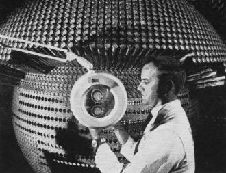
Hughes Aircraft Co. Radar phased array radar has antenna with
space-age "hair-do" look.
Nor has the Navy been dragging its feet, although so far, the carrier Enterprise
is the only place in which the Navy is employing phased array radar.
At present, and after some six years of operational tests, phased array radars
are still classified as experimental. But it won't be long before these radars become
regular inventory items by the various services.
In a typical phased array radar system, one set of antennas is used for transmitting,
another for receiving. Each system consists of hundreds, even thousands, of separate
antennas. The AN/FPS-85, for example, contains 5776 transmitting and 19,500 receiving
antennas.
The antenna sets can be subdivided into subsets, with each subset connected to
a receiver or transmitter. In some cases, each antenna is coupled to its own transmitter
or receiver.
All of the transmitters in a phased array system are on the air simultaneously
when a pulse is being transmitted. Since the output power of each transmitter is
additive, theoretically an unlimited amount of output power can be generated and
radiated.
To move the radar beam from one point to another, it is only necessary to change
the phase of the signal delivered to each antenna. The antenna itself remains stationary.
The result of all-electronic beam steering is inertialess tracking. Hence, the beam
can be steered from point to point in microseconds.
To provide the proper phase shift to each antenna at the high speeds required,
computers are used. In the case of the AN/FPS-85, three IBM computers are employed,
while HAPDAR employs a Univac computer.
Radar users are continually demanding more power, larger antennas, greater receiver
sensitivity, and the ability of the radar to keep track of the multitude of high-velocity
flying and orbiting objects. Such demands are mostly beyond the capabilities of
conventional radar techniques-but not beyond the capabilities of the phased array.
Parabolic radar antennas must conform to hard-to-meet mechanical tolerances and
are so heavy that enormous, impractical drive systems are required to overcome the
inertia involved in moving and re-positioning them fast enough to search for incoming
targets and simultaneously keep track of those targets already spotted.
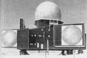
Conventional radars (Western Electric's DEW Line system shown)
are easy to identify.
Also, the waveguide that feeds the parabolic antenna limits the peak power that
can be transmitted by the system. Exceeding the power-handling capacity of the waveguide
results in inevitable breakdown. But even before this happens, the generation and
control of high voltages required to operate the super-power klystrons in radar
systems become serious problems.
The phased array radar overcomes another of the disadvantages of conventional
radars. Its thousands of active transmitters preclude system failure even if dozens
of transmitters are out of operation. (It has been estimated that in a given day,
as many as 100 transmitter modules fail in the AN/FPS-85 alone.) If a transmitter
fails, it can simply be unplugged and replaced by an identical unit.
Another important advantage of the phased array system is that virtually any
surface will accommodate it. In aircraft, consequently, better aerodynamic stability
and less crowding in the nose can be achieved when the radar is flush-mounted in
the fuselage. In space satellites, balance stability is obtained from the phased
array due to its lack of moving parts.
The basic principle of the phased array is not new. In fact it has been known
for many years that a directional beam can be formed with an array of antennas.
Only the technique of electronically varying the phase of the signal at each antenna
to obtain inertialess beam steering is new.
In operation, the signals from each antenna in a phased array form a wavefront
close to the array. Farther out, the wavefront forms a directional beam. Beam shaping
is determined by the number of antennas and their spacing within the array. For
the narrow beam essential to satellite tracking, a large number (the larger the
better) of antennas must be used. Conversely, for a broad-beam surveillance radar,
a few antennas are sufficient.
When the antenna elements are excited in phase with each other, the direction
of the beam is broadside to the face of the array. By introducing a different phase
displacement in the current delivered to each antenna, however, the beam can be
moved almost instantaneously from one position to another.
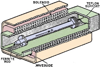
Phase shifter consists of a ferrite rod in waveguide. (Courtesy
of Bell Laboratories)
The phase shifter consists of a ferrite rod that is placed inside the waveguide
as shown in the drawing. This rod forms the center of a solenoid which is wrapped
around the waveguide. By varying the current through the solenoid coil, the permeability
of the ferrite rod is changed, thereby changing the velocity of propagation through
the shifter system. The result is that the delay in propagation causes a phase shift
in the transmitter's signal.
With a high-speed computer in control of the changes in current through the solenoid
coil, it is possible to create an almost unlimited variety of beam scanning patterns.
For example, the computer can be programmed to produce a beam that will "skip" a
nearby mountain but scan on both sides of the mountain for targets. Furthermore,
the high speed of the computer and low inertia of the radar beams make possible
tracking any number of objects in several different directions while at the same
time scanning for new targets coming into range.
Obviously, ponderous conventional radars with their enormous inertia cannot do
the job effectively. They are limited to the number of objects they can track simply
because they have to "pause" between pulse transmissions to wait for the return
echo before moving on. In the interim, they must remain idle.
A phased array radar, on the other hand, can transmit a pulse, move on to other
positions to transmit more pulses, and return to "listen" for the echoes from each
target spotted. Naturally, the closest targets are spotted first. During the receiving
phase, the appropriate amount of phase shift is applied to the signals being received
so that the signals add coherently. In effect, the received beam is "steered" in
a manner not unlike the steering of the transmitted beam.
Inertialess beam steering is not obtained without difficulty. Mutual coupling
between the radiating elements of the antennas in the array is a major problem.
Then, too, as the beam is steered or scanned away from boresight, spurious multiple
beams - commonly known as grating lobes - appear, giving the array a tendency toward
tunnel vision instead of the 180° scan angle it has in theory.
To scan a full 360°, it is necessary to use three or four phased array radar
systems-a factor that can multiply over-all systems cost well beyond so-called practical
cost/use limits. Phased array radars, after all, are not inexpensive. The total
reported cost of the AN/FPS-85 is $62,000,000. But this figure also includes the
cost of rebuilding the original system which was destroyed by fire in 1965 shortly
before it was to undergo operational tests.
The new techniques and devices (especially the use of IC's) just might cut the
cost of phased array radars dramatically. For example, RCA's Missile and Surface
Radar Division has already developed a solid-state phased array antenna design technique
which is said to yield power densities 100 times those of conventional radars. Texas
Instruments Inc. has developed a microradar so small that a complete transmitter,
receiver, and antenna can fit into the palm of a hand. And other companies - Sperry
Rand, Raytheon, RCA, Hughes Aircraft - are working feverishly to develop compact,
reliable, and low-cost phased array radars.
No matter what the cost of the phased array radar, it does a job that no other
type of radar can approach. For satellite tracking, defense surveillance, and insuring
air traffic safety, the phased array radar is a must. Bear in mind, however, that
no plans are on the drawing board to substitute the phased array where a conventional
radar will suffice. The conventional radars will be with us for a long time to come,
but they will eventually have to give way to the Space Age Radar - the phased array
- which has already proved itself.
Posted March 25, 2024
(updated from original post
on 12/11/2018)
|


