|
|||||||||||||
 |
|||||||||||||
Analog Logic
|
|||||||||||||
Whenever I read the April issue of any magazine, vintage or contemporary, lurking in my mind is whether it is an attempt at an April Fools "gotcha." The article title is usually the first clue that the author is trying to punk me at least provides a sporting chance. Take for instance this "Analog Logic" piece in the April 1972 edition of Popular Electronics. It could easily be a hoax, so I proceeded cautiously. It turns out to be completely legitimate. James Hannas provides a few examples of how analog circuits can be used to perform mathematical functions that are easily handled by logic circuits. Of course prior to the introduction of readily available, inexpensive digital integrated circuits only a few years earlier, all those mathematical functions were performed by analog circuits, so this was nothing new to most readers. If you have never researched the capabilities of both analog and mechanical computers, it would be worth your time; you will be amazed. One example that always impresses me is the electromechanical systems that pointed and stabilized the massive gun turrets on battleships during World War II. Analog Logic: It Takes More Than Flip-Flops to Make a Calculator By James Hannas
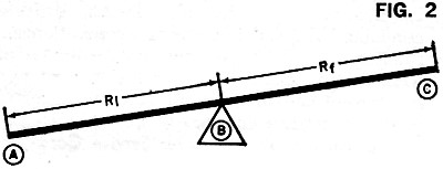
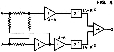
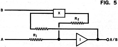
Have you ever wondered how some complex calculators can do so many operations at such high speed and accuracy? The answer is in the use of linear and non-linear integrated circuits that are basically quite simple in theory. Most of the circuits involve an operational amplifier - a very high-gain linear amplifier that inverts the input signal. When input and feedback resistors are connected to the op amp as shown in Fig. 1, the amplifier tries to maintain its input as close to zero as possible. The higher the gain, the lower the offset or error voltage. To do this, the amplifier must cause a current through the feedback and input so that the voltage drop across the input resistor is equal to the input voltage. The input swing is equal to the input voltage times Rf/Ri. A graphical analogy of the amplifier is shown in Fig. 2. Using the same circuit, but with additional input resistors, the amplifier can be made into an adder. The sum of the voltages can also be multiplied by a constant by adjusting the input resistors. Nonlinear functions, such as squaring, can be performed by the diode shunt matrix shown in Fig. 3. By adjusting the feedback resistors, any type of curve with increasing magnitude can be formed. A logarithmic, or decreasing, curve will result when the diode matrix is used as a feedback instead of a shunt matrix. The most common squaring circuit is shown in Fig. 4. The numbers on the op amps indicate the multiplier constants. By adding one quarter of the sums of A-B and A+B, the result is the product of A and B. Division is shown in Fig. 5. Here an op amp is supplied feedback by a multiplier circuit which is controlled by B. As B increases, the output decreases. There are also operational amplifiers and multipliers which are binary-to-analog and analog-to-binary converters. These are basically resistor networks and amplifiers. By combining analog circuits with binary bit storage, switching and readouts, a compact calculator can be designed.
Posted March 2, 2023 |
|||||||||||||
 |
|||||||||||||
|
|||||||||||||


|
||||||||||||||||||||||||||||||||||||


