|
|||||||||||||
 |
|||||||||||||
V.L.F. Loop Antenna
|
|||||||||||||
If you have been searching for a do-it-yourself VLF loop antenna that can be resonated from approximately 14 to 25 kHz, then look no more. This article from a 1963 edition of Electronics World magazine presents a relatively simple to build job that reportedly provides excellent reception. At these frequencies a wavelength is measured in miles, which makes even a simple dipole antenna impractical, so the multi-turn loop is the only reasonable alternative for most people. It is the same principle that allows the little ferrite-core antenna inside your AM radio to work so well when the shortest wavelength in the commercial AM broadcast band (535 - 1700 kHz in the U.S.) is nearly 600 feet. V.L.F. Loop Antenna
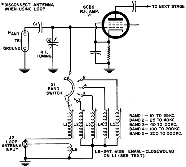
Fig. 1 - Schematic of loop with its tuning and matching network. By Richard A. Genaille Construction of a simple, low-cost sensitive loop ideally suited for good low-frequency reception. The very-low frequencies from 3 to 30 kilocycles have experienced a resurgence of use and interest about which many persons engaged in electronics are not aware. The September, 1961 issue of this magazine carried an article ("Below the Broadcast Band") in which the author described some of the activities which are taking place in the very-low and low-frequency bands and also a simple low-frequency converter which could be constructed for the reception of these frequencies. Briefly, the very-low frequencies are providing a means of high-accuracy frequency determination in much shorter periods of time than is normally possible on the higher frequencies, and also the means by which the U. S. Navy transmits messages to submerged submarines which are scattered throughout the oceans of the world. Present and proposed activities relative to the v.l.f. region will be discussed later in this article. So fascinating and useful have the very-low frequencies become that the author decided to upgrade his receiving antenna system for v.l.f. by constructing a loop antenna which would greatly improve signal-to-noise ratio and would discriminate against adjacent-channel interference. A considerable amount of experimentation produced a v.l.f, loop antenna that, you will discover, is simple to construct, efficient and inexpensive, and which has all of the desirable electrical features that a loop antenna should have. While the loop to be described was constructed for use in conjunction with the low-frequency converter featured in the aforementioned article, it has been designed with a feed-point impedance of 52 ohms to accommodate standard 52-ohm coaxial transmission line and the input impedance of some receivers. It may be used on other very-low frequency converters or receivers having other than a 52-ohm input impedance by the simple expedient of impedance matching. Since receiver input impedances can vary considerably, the author will describe the method used to impedance-match to his converter as well as several simple methods of matching to other input impedances.
Fig. 2 - Construction of the bifilar-wound balanced transformer.
Fig. 3 - Bridge method of measuring s.w.r. when tuning antenna. The decision to construct a loop antenna for v.l.f, in preference to using a random length long wire or a simple half-wave dipole was made after realizing that such antennas have several undesirable characteristics. Providing that the long wire was made long enough to have definite directional characteristics, it would be quite difficult to make use of the directional features because of the problem of positioning the antenna. The long wire is inferior to a loop antenna for minimizing noise pickup. A simple half-wave dipole at 20 kilocycles would be approximately 4 miles long. To keep the v.l.f. antenna to a reasonable size and to provide directional selectivity and noise reduction were factors which led to the choice of the loop antenna as the most satisfactory solution to the antenna problem. Since loop antennas are not as commonplace as the "garden variety" of directional antennas, such as multi-element directive arrays for amateur radio and TV use, a few words regarding loop antenna operation may be in order for a better understanding of the constructional details to follow. Loop-Antenna Operation Loop antennas have been widely used for many years in direction finding systems particularly aboard aircraft and vessels. The function of the loop is to sense the direction of the arrival of radio signals emanating from a transmitter at a fixed location. The basic loop antenna is simply a coil of wire whose diameter is small in comparison to the wavelength to which the coil is tuned. The ground-wave transmission from the very-low frequency station causes vertically polarized waves to induce voltages in the loop wire as these waves pass by the loop. The induced voltages in the loop wire produce a loop current which depends upon the positioning of the loop antenna with respect to the wavefront. Almost any convenient shape can be used for a loop antenna, such as a square, triangle, octagon, or diamond. But regardless of which shape the loop assumes, the maximum directivity is along the plane of the loop with a distinct minimum or null at right angles to the plane. The directive pattern of a loop whose diameter is small with respect to the wavelength to which the loop is tuned is similar to that of a doublet antenna, that is, a figure-8 field pattern. The minimum or null, which is broadside to the plane, is extremely sharp in a well-designed loop antenna and is normally capable of giving bearing information better than one degree in low-frequency direction finding work. While the purpose of constructing the loop antenna, in this case, is not that of direction finding, the presence of a sharp null at zero and 180 degrees with respect to a fixed v.l.f. signal source a reasonable distance away indicates that the loop is functioning properly. This will make it possible for us to eliminate undesirable adjacent-channel interference. The absence of this sharp null broadside to the plane of the loop antenna can be caused by locating the antenna too close to power wires, other antennas, gutters and downspouts, or other metallic objects and, in general, by poor symmetry of the entire loop antenna circuit including the transmission line and receiver input. The use of a balanced feedline arrangement and a push-pull r.f. stage for the receiver input or a suitable-matching transformer to match between a balanced feed point and an unbalanced line can be accomplished to improve loop circuit symmetry. Static electricity in the air is a source of much noise in low-frequency reception and very often causes complete masking of desired signals. Enclosing the receiving loop wires in a non-magnetic metallic shield will greatly reduce noise pickup thereby enhancing the over-all signal-to-noise ratio of the receiving system. The loop wires are completely surrounded by the shield except for a narrow transverse gap or break at the apex of the loop electrostatic shield. Circuit Arrangement The v.l.f. loop antenna shown in the photograph can be resonated from approximately 14 kc. to 25 kc. with the components specified in the schematic diagram. In this range the feed point impedance will be 52 ohms. The construction of this antenna is quite simple and straightforward and the cost of the materials used represents a very small investment of the performance obtained. All of the component parts of the loop antenna circuit are readily available. The schematic of the v.l.f. loop is shown in Fig 1. L1 is continuous loop made up of 18 turns of #16 enameled or form-var-insulated wire. L2, which is adjustable from 0.2 to 3 mhy, is used to resonate the loop circuit to the desired frequency. T1 is a matching transformer wound so that loop balance is maintained while providing a match to a 52-ohm unbalanced line. Capacitors C1 and C2 are good quality micas used to bring the over-all loop tuning into the range of tuning coil L2. The tuning coil, capacitors, and matching transformer are housed in an aluminum box with dimensions of suitable size to permit freedom in making the necessary connections. The electrostatic shield for the loop wires is made from a twenty-five foot length of soft-drawn copper tubing with a 1/2-inch inside diameter. This tubing is available from Sears, Roebuck or any plumbing supply house. In many cases 25 feet of tubing represents a standard length coil and was chosen so as to avoid wasted tubing due to cutting. A length of cheap plastic hose with a 3/8-inch i.d. and slightly less than a 1/2-inch o.d. was used inside the copper tubing to protect the loop wires during the pulling operation. The author felt that the small extra cost of the plastic hose would be worth it to prevent possible abrasion of the wire insulation and subsequent operational troubles. The plastic hose also provides additional loop rigidity lost by the necessity for a gap in the copper tubing at the apex of the loop. Construction Details
The author's loop must presently be turned by hand although it is planned to install an antenna rotator for it shortly.
One end of the loop just prior to its being tied into the box.
Fig. 4 - An s.w.r. bridge modification for improved v.l.f. use.
Inside view of the aluminum box. A terminal board or a piece of insulating material with holes drilled into it can be used to support the connected ends of the No. 16 loop antenna wires. The first step in the construction of the loop proper is uncoil and stretch out the 25 feet of copper tubing on a level floor. The straighter the tubing the easier it will be to pull through the plastic hose and wires in the following steps. After the tubing has been straightened, solder a 1/2-inch copper tubing-to-outside thread adapter to each end of the tubing. Conduit nuts of suitable size may be used to secure the copper tubing to the metal box which houses the smaller circuit components. Next, measure to the exact center of the length of tubing and, using a tubing cutter, cut the tubing in half. Keeping the tubing sections together, insert a 27-foot length of plastic hose into one end of the tubing and, by working it slowly, pass the hose through both sections of the tubing so that approximately one foot of hose remains outside each end of the copper tubing. At this point a single #16 wire should be worked through the tubing-hose combination to facilitate pulling through the bundle of 18 #16 loop wires. The loop wires should be cut to a length of 27 feet and each wire tinned on one end. The bundle of eighteen wires should then be soldered to the pulling wire and the bundle carefully pulled through the entire length of the loop tube. Incidentally, the tedious job of removing the insulation from the wire ends can be simplified by using some Sears, Roebuck No. 2779 Paint and Varnish Remover. The simplest way to form the loop is to layout a circle 8 feet in diameter on your basement or garage floor. Use a heavy marking pencil so the outline may be easily seen. A word of caution, don't construct the loop in the basement if you can't get it out of the basement doorway. In bending the tubing the author found that the 100 or so pounds of his 13-year-old son standing on the tubing prevented the tubing from moving as the circle was being formed. After the circle has been formed the plastic hose and wire should be cut back as shown in the photograph. Suitable holes may now be drilled in the metal box and the tubing ends fastened to the box with the conduit nuts. A terminal board was installed in the metal box in order to facilitate connecting the 36 wire ends into a continuous loop of 18 turns. Connecting the wires properly can be accomplished by using an ohmmeter or they can be "buzzed out" by use of a dry cell and buzzer or pilot light bulb. If care is exercised the center turn of the multi-turn loop can be identified and marked at the time that the loop wires are being soldered together to form the continuous coil thus avoiding the trouble of trying to determine the loop center by electrical measurement. The loop wire resistance is quite low, approximately 1 3/4 ohms, and it is quite difficult to make accurate measurements in the low resistance range of the ordinary ohmmeter. After the loop wires are all connected, except for the two ends, tuning coil L2 can be mounted and connected in series with the loop wires at the midpoint. Capacitors C1 and C2 can be mounted and wired except for the connection to be made to the matching transformer T1. A suggested layout for the various components that are installed within the metal box is shown in the photograph. Line-matching transformer T1 is an important part of the loop circuit in that it provides the impedance transformation required while maintaining loop balance. Reasonable care should be exercised in winding T1. The ferrite rod from a transistor-radio loopstick was used as the core for this transformer. The original windings were removed and 180 turns of #28 enameled wire close-wound on the core. This winding will be the secondary and will connect to the coaxial output connector J1. To determine how much wire will be required for the primary and how much space will be taken, wind 104 turns of #28 enameled wire over the secondary. Remove the 104 turns of wire and after finding the center of this length of wire, fold the length of wire in half so that the wire is doubled. Now take the doubled wire and wind 52 turns over the 180-turn secondary. Care should be taken to center the primary winding over the secondary in order to maintain balance. By connecting the wires of the primary as shown in Fig. 2 we will have a bifilar primary which will have equal capacities from its ends to ground. Some coil dope can be applied to the windings of T1 keep the wires in place. When the line-matching transformer has been completely fabricated it should be installed in the metal box and wired into the loop circuit. The loop antenna proper is now electrically complete and should be mounted in a manner convenient to the builder. The author used a combination of aluminum tubing, bamboo, and TV-type antenna clamps to construct the supporting cross members. Be careful not to use a solid metallic framework to support the loop since the electrical operation of the loop may be seriously affected by shorting across the electrostatic shield. A piece of steel tubing was used for the lower part of the mast and this piece of tubing was inserted into a slightly larger piece of tubing which had been driven in the ground. As shown in the photograph of the loop, the "Armstrong" method of rotating the loop was used; however, the author plans to install a TV antenna-type rotator in the near future. Tuning and Impedance Matching Tuning the loop to resonate at a particular frequency in the 14 kc. to 25 kc. range is not much of a problem. It is accomplished in the same manner as tuning and impedance matching of higher frequency antenna systems. A simple block diagram of the set-up used by the author is shown in Fig. 3. The standing-wave-ratio bridge used for adjustments is a home constructed bridge typical of those described in any of the popular radio handbooks. The audio signal generator used was a Heathkit AG-9 with a range of up to approximately 100 kc. Before starting the adjustment procedure it would be wise to check the bridge to be used for satisfactory operation on the very-low frequencies. If the bridge is to be used to check a 52-ohm termination, connect a 52-ohm resistor to the output or line side of the bridge and feed a signal of about 20 kc. into the bridge. If, with the correct load, the bridge indicates reflected signal, make the modification to your bridge as shown in Fig. 4. The bridge should then operate satisfactorily on the v.l.f. band.
Fig. 5 - Circuit modification to the author's v.l.f. converter. With the bridge and signal generator connected to the antenna, as shown in Fig. 3, set the generator to deliver output at the frequency to which the loop antenna is to be resonated. Adjust the loop tuning coil L2 until the reflected power reading on the bridge reads a minimum. On the author's installation it was possible to obtain a zero reading of reflected power on the bridge at all frequencies between 14 and 25 kc. Impedance matching to the converter or receiver with which the loop antenna is to be used can be accomplished in a number of ways. A satisfactory match to the author's converter was made by winding 24 turns of #28 enameled wire on the converter v.l.f. coil L1, as shown in Fig. 5. The coupling loop is wound as close as possible to the original winding and on the slug adjustment side of the coil. The converter v.l.f. coil was remounted on the upper side of the chassis since it was found that a noticeable amount of signal strength was lost by under-the-chassis mounting. The same mounting hole was used and several smaller holes were drilled in the chassis to accommodate the grid and coupling coil connections which were run under the chassis. In addition, a u.h.f.-type coaxial connector was installed on the chassis to connect to the loop antenna transmission line. For the different input impedances which may be encountered one may find it convenient to use one of the ultra-compact high-fidelity audio transformers manufactured by UTC. The UTC type A-24 or A-26 has a response of from 20 to 40,000 cycles with a primary impedance of 15,000 ohms and 30,000 ohms respectively. The secondary impedance for both of these transformers is 50, 125-150, 200-250, 333, and 500-600 ohms as required. By using either one of these transformers in reverse it is possible to make a transformation between the low impedance 52-ohm line and the high-input impedance of a converter or receiver. Another alternative in obtaining a higher feedpoint impedance for the loop antenna is to replace capacitors C1 and C2 and line-matching transformer T1 with a single .015-μf. capacitor to close the loop coil. When the loop is resonated by the use of tuning coil L2 one may tap at two points, one on either side of the loop electrical center and each equidistant from the center, and obtain a balanced feedpoint that is higher in impedance than 52 ohms. On the author's loop, tapping of the first two loop turns on either side of center gave a feed point impedance of 150 ohms. This impedance could conveniently fed by the use of two 75-ohm coaxial cables with the shields tied together and the inner conductors connected -one each to each loop tap. Since the loop turns are accessible in the miscellaneous components box it is quite convenient to tap in this manner to find a satisfactory feedpoint. Operation and Results Operation of the v.l.f. loop antenna needs very little comment. You will notice, after a trial "spin," that the loop exhibits two very sharp nulls broadside to the plane of the loop and that you have a much improved signal-to-noise ratio. Comparative checks can be made which will vividly demonstrate the superiority of the loop over that random long wire that you may now be using. Stations now being heard by the author on the v.l.f. band include the U. S. Navy's precise frequency-controlled transmitters such as NAA at Cutler, Maine on 14.7 kc., NBA (Summit, Canal Zone) 18 kc., NPG/NLK (Jim Creek, Washington) 18.6 kc. and others. WWVL, the National Bureau of Standards' frequency-standard station, which operates on 20 kc. from Sunset, Colorado can be heard but not nearly as loud as the Navy "giants" which run in the neighborhood of two million watts of power to their antennas. Several foreign stations, such as GBR in Rugby, England on 16 kc. and FUB near Paris, France on approximately 17 kc., are being heard consistently. Future plans for the very-low frequencies include the construction of a new Navy transmitter to be located in Australia which will undoubtedly be in the multi-megawatt class and a proposed NATO station which will operate on 19 kc. Recent tests using satellites have disproven the belief that the ionosphere was a shield for the very-low frequencies with the result that consideration is now being given to the use of these frequencies for communicating between earth and outer space. The ultra-low frequencies recently produced some astounding results when a 400 cycle-per-second signal was transmitted a distance of approximately 750 miles from Boron, California to El Paso, Texas in tests conducted by the Air Force. The very-low and low frequencies are, to be sure, more fascinating than ever before. Constructing the novel v.l.f. antenna described in this article will assure you of greater success and listening pleasure while exploring the very-low frequencies. |
|||||||||||||
 |
|||||||||||||
|
|||||||||||||


|
||||||||||||||||||||||||||||||||||||


