|
|||||||||||||
 |
|||||||||||||
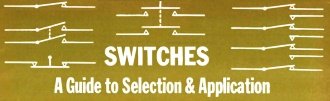
Switches - A Guide to Selection & Application
|
|||||||||||||
Arthur Hackman's 1967 Electronics World magazine article provides a systematic guide for selecting mechanical and manual switches, beginning with specifying the required function through poles (circuits controlled) and throws (positions connected, excluding "off"). Voltage and current ratings must not be exceeded to prevent contact welding or catastrophic dielectric failure. Mechanically actuated switches include pressure-sensitive types (with defined proof and burst pressures), temperature-sensitive switches, and various limit switches (plunger, lever, roller), which require consideration of mounting and environmental sealing for harsh conditions. Manually actuated switches - push-button, rotary, toggle, and slide - demand ergonomic design, including logical placement, appropriate actuation force, and standard color identification (e.g., red for urgent functions). The core principle is to use standard, commercially available switches whenever possible, as most applications do not justify custom designs, ensuring a balance of electrical capacity, mechanical actuation method, and operator interface for reliable performance. Switches - A Guide to Selection & Application
Important factors for mechanically and manually actuated switches are presented as a practical aid in choosing the best switch for the job. When trying to decide what switch to use, your first questions must be "What function do I want the switch to perform? Will it be used to switch one circuit, two circuits; to switch electrical power to one load, two loads, or to one of several loads?" The answer must include the number of circuits and the number of loads, or the number of poles and the number of throws which make up part of the switch description. The word "throw" is not to be confused with the word "position" since "position" includes any "off" position that may exist. Hence a simple single-pole, double-throw switch can switch the power of one circuit to either of two loads and may be equipped with two, or with an "off," three positions. If a switch is to be kept in some particular position, this too is reflected in the description, such as single-pole, single-throw, normally open. Standard terminology and circuit arrangements are illustrated in Fig. 1. Those for rotary and other types of switches will be covered later in this article.
Fig. 1 - Popular contact configurations and circuit terminology.
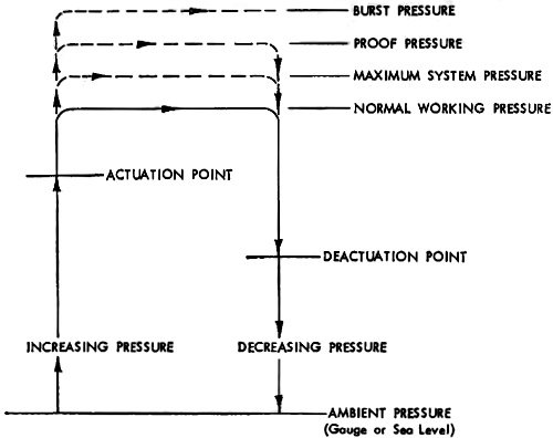
Fig. 2 - Schematic operating cycle of a gauge pressure switch.
Fig. 3 - Terms describing operation of limit switches are shown.
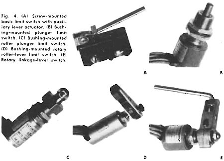
Fig. 4 - (A) Screw-mounted basic limit switch with auxiliary lever actuator. (B) Bushing-mounted plunger limit switch. (C) Bushing-mounted roller plunger limit switch. (D) Bushing-mounted rotary roller-lever limit switch. (E) Rotary linkage-lever swatch.
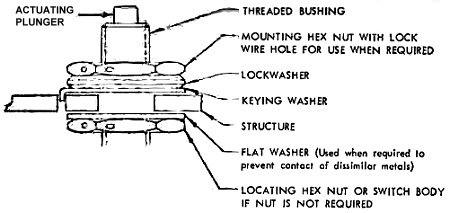
Fig. 5 - Accepted installation of a bushing-mounted switch.
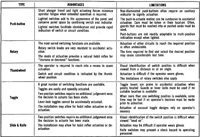
Table 1 - Comparison of manually actuated switches with their main advantages and limitations.
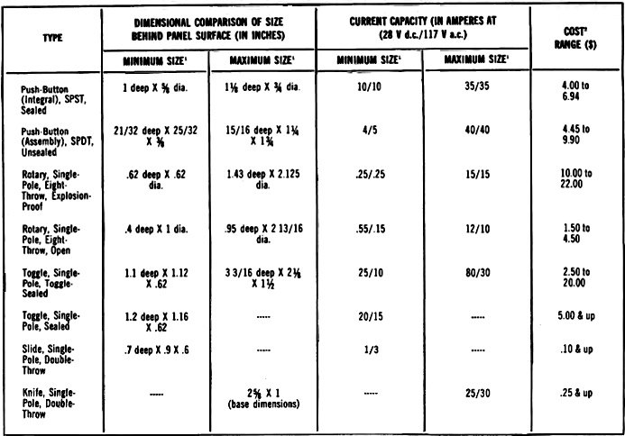
Table 2 - Characteristics of a cross-section of available manually actuated switches of various types.
Fig. 6 - (A) Push-button assembly. (B) Integral push-button.
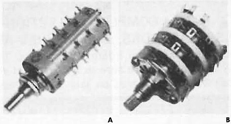
Fig. 7 - (A) A typical explosion-proof rotary switch is shown here. (B) More common open rotary switch.
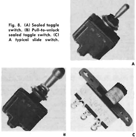
Fig. 8 - (A) Sealed toggle switch. (B) Pull-to-unlock sealed toggle switch. (C) A typical slide switch. Voltage and current ratings must also be considered. The electrical ratings of the switch should not be exceeded if satisfactory operation is expected. It is not necessary to derate or use a percentage of the rated current of the switch of a reputable manufacturer. However, if greater electrical life is desired, the manufacturer can probably recommend a reduced current that will increase switch life. Current overloads decrease switch life: sufficiently high or consistent overloads cause early switch failure by welding the contacts. Over-voltage also decreases switch life. Ultimate switch failure from overvoltage results because the switch is unable to interrupt current flow after the contacts have separated. Voltage or dielectric failures are usually catastrophic, sometimes resulting in an explosion. Often, minimum levels of voltage-current are overlooked but when values are expressed in millivolts and microamperes it is wise to determine and specify the maximum acceptable voltage drop at the rated load across the contacts. Usually gold contacts are specified for such applications, but this should be checked with the manufacturer or your company's switch specialist, if there is one. There are many advantages in using off-the-shelf switches. The fact is that the vast majority of applications can be handled without the need for a specially designed switch. Admittedly, the state of the art would never advance without new designs, nevertheless an attempt should be made to use existing switch designs whenever and wherever possible. After determining what circuit configuration and electrical capacity is required, the next choice involves the method of actuation. This choice falls into two categories: 1. mechanically actuated, and 2. manually actuated switch. Mechanically Actuated Switches Very often an engineer will find that the mode of mechanical actuation is dictated by his design, that is, the medium sensed is also the actuating medium. The majority of these switches fit into the following categories: pressure sensitive switches, temperature-sensitive switches, and position-sensitive or limit switches. Pressure-sensitive switches are used when specifications require changes in fluid pressure to be monitored or controlled. Switches are available to cover a wide range of pressures - from those of over 25,000 psi to pressures expressed in fractions of an inch of mercury. Generally speaking, the actuating mechanism of pressure switches incorporates a pressure -sensitive diaphragm coupled to an electrical switch. Actuation of the switch occurs within a specified range of pressures. Similarly, deactuation occurs within a specified range of pressures. This range includes the actuation (or deactuation) point plus a tolerance which will vary widely, depending upon the accuracy required and the pressure range of the switch. Good engineering practice demands that only the required accuracy be specified as the tolerance, not the best available. The deactuation point is the pressure at which the switch mechanism resets and, as a general rule, occurs at a lower pressure than that which caused actuation. Sometimes, the terms of actuation and deactuation are interchanged, depending on the primary application of the switch in question. The proof pressure is the maximum pressure that can be applied without a calibration shift in the actuation and deactuation points. Good design requires that the proof pressure of a switch be a minimum of one and a half times the maximum system pressure. The burst pressure of a pressure switch is the maximum pressure to which the switch can be subjected without rupture or damage. Usually, burst pressure is two to two and a half times the pressure in the system under normal operating conditions. Fig. 2 shows schematically an operating cycle of a gauge pressure switch and illustrates the terms just discussed. The different types of available pressure switches include: 1. altitude or 48 absolute pressure switches, 2. differential pressure switches, 3. vacuum switches, 4. altitude switches, and 5. absolute pressure ratio switches. Temperature-sensitive switches are used to protect against over -temperature, indicate an extreme temperature, or control at a specified temperature. The characteristics and behavior of thermal switches are similar to those of simple pressure -sensitive switches except that they are operated by changes in temperature. Actuation and deactuation occur in a similar manner. They are available with ranges from -100 °F to +500 °F. Switches with smaller ranges are also available with tolerances approaching ½°F. The range of the switch is a function of application, and tolerance or temperature differential will depend on the accuracy required. Limit or position-sensitive switches are used to actuate or deactuate equipment relative to cam position or door location. Very often limit switches are multicircuited to actuate signal lights to indicate the condition of the equip - Silent. Types of limit switches vary according to the type of actuation, including lever, plunger, roller plunger, rotary roller-lever, and rotary linkage-lever, and non-contacting switches. Non-contacting or remote sensing switches perform the same function as other mechanically actuated switches but without physical contact. These include proximity, photovoltaic, photoelectric, or pneumatic devices acting as sensors coupled with amplifiers or relays to perform the switching functions. Since their use is largely confined to automated machinery, they will not be discussed here. Plunger-actuated limit switches allow the greatest range of applications, but are restricted to inline actuation with controlled overtravel. If the overtravel is not controlled, the switch may be damaged if the force is sufficient. (The actuation point of bushing-mounted plunger switches can be set by means of the two hex nuts supplied with the switch. Often, due to the normal build-up of tolerances, the exact position of actuation cannot be predetermined. It is then necessary to adjust the nuts by a cut-and-try technique to locate the exact actuation point of the switch.) Operating characteristics applying to limit switches are shown in Fig. 3. The most popular mounting means are: 1. bolt or screw-mounted as in Fig. 4A or 2. bushing-mounted as in Fig. 4B through E. The bolt or screw-mounted limit switch is essentially restricted to basic switches, with most sealed limit switches being bushing- mounted. Sealed limit switches can be designed to operate in almost any environment. They are often watertight to the extent that moisture cannot be pumped into the switch through cycles of pressure or temperature with the resultant condensation. Some sealed switches, for example, are subjected to environments that build up ice on the actuating plunger. An integral part of the switch, called the "ice scraper," acts to clean the plunger upon actuation and free it of ice. If the switch has been held actuated and the actuating force is removed, the release force built into the switch acts to break the ice barrier. Lever actuation is most often employed with a basic switch, as shown in Fig. 4A. Advantages include its compact size, ease of installation, general lack of tight tolerances, and its flexibility of application with additional actuators. Its main disadvantage is its vulnerability clue to a lack of protection. A roller-plunger limit switch is a slight modification of the plunger limit switch (Fig. 4B) for adaptation to cam or slide actuations which have an incline or rise of less than 30 °. An example is shown in Fig. 4C. Often the roller plunger has an adjustment mechanism that allows locking the roller in 45° increments. Cam or slide actuation with an incline of more than 30° requires a rotary roller-lever actuation, the type shown in Fig. 4D. This type of actuation usually operates in only one direction and is spring-loaded to return the lever to a neutral or deactuated position after the operating force is removed. A modification of the rotary roller-lever switch is the rotary linkage-lever (Fig. 4E) which is used to physically connect the actuating device to the switch. This switch operates in both directions but has no return spring. The linkage-lever is threaded so it can be attached to the actuating device which must provide the deactuating as well as the actuating forces. The actuation point of both rotary lever switches is positioned by a worm gear with a screw adjustment that locates the arm in any position through 360°. Mounting of rotary-lever switches is often similar to that of plunger switches except the axial positioning of the switch is not as critical and, for this reason, only hex nut is used. Fig. 5. shows an accepted method of installing a bushing-mounted switch. Note that the keying washer is placed on top of the structure to serve the dual purpose of keying the switch and protecting the structure from the lock washer. An alternative to the keying washer, as used by some switch manufacturers, takes the form of two tabs projecting above the switch body which engage two mating holes in the mounting. In areas of extreme vibration, a lock wire is used to prevent loosening of the mounting nuts. Manually Actuated Switches A selection of manually actuated switches offers the designer a little more leeway in his circuit than mechanically actuated switches. Personal preferences may sometimes influence switch selection since a goodly number of applications can be handled by more than one type of switch. Table 1 compares applications while Table 2 compares parameters of a number of different manually actuated switches. The application of a manually actuated switch simply conveys a message from the man to the machine. The man/ machine concept involves several considerations. Since the design of the machine interface is the more flexible, the switches involved must be selected and applied to fit the operator. The considerations involved are: 1. physical location, 2. mode of actuation, and 3. identification of the switch. Actuating levers and knobs that are most often used should be in close proximity to the operator's normal position. The switch in the control panel should be positioned so that the operator's clothing won't accidentally cause actuation. The switch should also be located so that it is not inadvertently actuated. If this is not possible, protect the actuator with a guard. Ideally, if several switches are mounted on a single panel, they should be spaced far enough apart to avoid accidental actuation of a switch due to its proximity to another. Consideration should also be given to the environment in which the switch will operate. Even though performance, life, and reliability can almost always be increased by improved sealing, this often carries a prohibitive price tag. For this reason, economics usually dictates selection of the least amount of sealing that can do the job. In addition to the obvious case of selecting a sealed switch if water may drip or splash on it, a sealed switch should also be selected if it will be exposed to extremes of temperature or some other environment that might cause moisture to penetrate the switch when the environment is a non-operating one. Flexible rubber seals or boots are available to aid in sealing a switch between the actuator and mounting bushing and/ or mounting panel. The mode of actuation should be consistent with habit reflexes, e.g., actuate a toggle in the upward of forward direction to bring machinery up to full speed, or push a button to test for some condition. The effort required for actuation may sometimes be related to the switch application. For example, when switches will be actuated at high speeds and for long durations, a light actuating force is recommended. It is also desirable that some form a feedback, an indicating light for example, be designed into the circuit if the switch does not provide some audible or operational indication of actuation. Assuming the switch is in working order, the positive "snap" of actuation or sudden reduction of operating force will often be sufficient evidence of actuation. Printed or lettered identification of the switch should be within reading distance and numbers or letters associated with the switch should be located in such a way as to allow reading when the operator is in his normal position. Sometimes an unusual shape of a knob or handle may be employed to help the operator make the proper selection quickly, but this type of design is generally not recommended as it relies on the operator's memory. The majority of manually actuated switches fit into the following four categories: push-button switches, rotary switches, toggle switches, and slide and knife switches. Push-button switches are of two general designs: either a basic switch (or switches) mounted in a push-button housing, Fig. 6A, or an integral push-button switch, Fig. 6B. The switching chamber of the first design is simply that of the basic switch, often enclosed but unsealed. The integral push-button switch has a housing that is usually water-sealed at the plunger and environmentally sealed at the terminals. Both groups are further subdivided into lighted and unlighted push-buttons, with several possible identifying colors available. Unlighted push- buttons should be colored black. Lighted push-buttons should be red, green, amber, white, or blue. Requirements for the application of identifying colors as indicators are as follows: Red: The circuit controlled by the switch requires immediate attention, e.g., a portion is inoperative or corrective action must be taken. Green: The circuit controlled is in satisfactory condition, e.g., the equipment is within operating tolerance. Amber: The circuit controlled is in a marginal operating condition, caution may be required. White: The circuit is operating satisfactorily with no "right" or "wrong" implications. White is often used to convey some additional information to the operator. Blue: Blue is used to indicate radiation hazards but is generally accepted as an alternative to white. Blue should be used only when absolutely necessary since it doesn't show up well. Push-buttons are available with maintained actions and momentary actions, the former requiring a second plunger operation to complete the cycle. Push-button switches should be used when a control or array of controls is needed for momentary contact or for test functions or when used frequently. The push-button surface should be concave or designed so as to prevent the fingers from slipping off the control. Since there is no knob or lever position to indicate a maintained push-button's actuation, lighted push-buttons are usually preferred. Non-illuminated push-buttons may be used with an auxiliary pilot light but this decreases system reliability and may cause the operator to search for the proper indicator light. Rotary switches can be classified according to the type of sealing-closed or open, with further sealing classifications in the sealed category. The most popular sealing of a closed switch is explosion-proof, that is, the rated load can be switched in an explosive atmosphere without causing the switch to explode. See Fig. 7A. This enclosure is not watertight to immersion, but is sufficiently tight to prevent water penetration in most applications. Often a rotary switch is made with a rubber "O" ring between the shaft and bushing to prevent moisture from entering the switch through the bushing. The advantage of a closed rotary switch, like that of other switches, is the protection afforded by its enclosure. However, open rotary switches offer an advantage, besides cost, that is very desirable in some applications. See Fig. 7B. The accessibility of the switching contacts allows visual inspection of their condition and even repair. Rotary switches should be used when the circuitry involved requires more than three positions. They should not be used when only two positions are needed. Momentary actions are available in addition to maintained actions. Rotary switches can switch current to as many as 24 loads or with as many as 12 poles or circuits per deck. The number of poles can be increased by a factor of 3 or 4 by using several poles per deck at the expense of the number of loads. The common contacts (poles) of each circuit may be either shorting or non-shorting. A shorting contact activates the next circuit during each switching cycle before removing power from the last circuit. A non-shorting contact supplies power to only one circuit at a time. Switches with concentric shafts are useful where a small package is essential. Two switches are combined into a single unit with two distinct shafts. Combinations of shorting and non-shorting contacts along with varied numbers of loads and poles are available. However, complex designs of this nature reduce system reliability, operator efficiency, and tend to degrade the over-all system effectiveness and should be avoided if possible. Round black knobs are frequently specified. Consideration must also be given to the depth of the recess in the knob with the length of actuator shaft of the switch and any possible interference with the mounting panel ( and face plate if one is used) or the switch identification. Included in rotary switches are thumbwheel switches. These are rather specialized in their application and are usually used in conjunction with circuit boards. Most often the thumbwheel switch has ten position with the output digital or binary coded. Toggle switches are classified according to their number of poles, with each group being further divided according to the sealing. Usually toggle switches have one, two, or four poles; three -pole switches are available but do not enjoy the same usage and popularity. The sealing is: 1. unsealed with varying amounts of enclosure; 2. toggle-sealed, that is, when submerged with water one-half inch above the bushing, water will not enter the switch through the toggle seal; or 3. environmentally sealed, that is when submerged completely and subjected to pressure equivalent to 56,000 feet altitude for several hours, depressurized, and allowed to remain under water for several more hours, water will not be pumped into the switch. An environmentally sealed toggle switch is shown in the photograph of Fig. 8A. Toggle switches should be used in applications requiring two or three positions. Generally, in a three-position toggle switch the center is the "off" position with the extremes representing circuitry "on" conditions. These switches are also available with "momentary-on" positions. Toggles with more than three positions should not be used. When more than three positions are required, a rotary switch should be specified. A very popular safety feature, often selected as an alternative to a switch guard, is the "pull-to-unlock" toggle lever, Fig. 8B. A spring-loaded cap or knob on top of the lever requires the operator to lift it manually to allow movement to another position. Guards are available ranging from complete enclosures of the toggle to channel-shaped guards that require the operator to reach into the channel and actuate the switch. Slide and knife switches are the most basic, simple, and reliable of the manually actuated switches. A slide switch is shown in Fig. 8C. Almost without exception they are unsealed. They are usually enclosed or provided with some form of housing to protect the operator. As with any switch, special functions, hybrids, and accessories are available. The most popular slide and knife switches are used where economy is a major consideration. Their application is limited to environments that do not require sealing, except those knife switches used in outdoor fuse boxes which are usually classified as rain-tight. Their function is similar to that of toggle switches. Standard Switches Almost any number of variations on the switches discussed here are available - unusual or untested parts should be avoided. Such a selection most often contributes little or nothing to the system effectiveness. A hard and fast rule which will enable a designer to determine if a switch will function properly in his application usually does not exist. The only criterion is the establishment of the application requirements and then the selection of a suitable switch which will meet those requirements. |
|||||||||||||
 |
|||||||||||||
|
|||||||||||||

 By Arthur F. Hackman
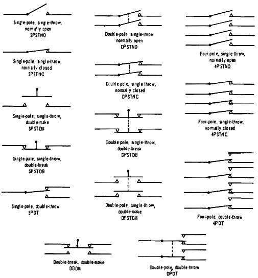


|
||||||||||||||||||||||||||||||||||||


