|
|||||||||||||
 |
|||||||||||||
Electronically Steerable Antenna
|
|||||||||||||
This article describes an electronically steerable aperiodic loop antenna developed that claims superior beam pinpointing on targets with high gain in minimal space for high-frequency signals (2-32 MHz) via ionosphere, akin to linear arrays. Comprising 36 untuned balanced loops, each about 1 meter in diameter with transistorized preamplifiers, arranged on a 150-foot (50-meter) circular perimeter, the system weighs roughly 12 pounds per element and withstands 100 mph winds. Phase shifts enable simultaneous beams every 10° through 360°, or commutator scanning for direction finding, equating to 18 rhombic antennas at 10° intervals. The flat frequency response ensures constant effective height over four octaves and precise phasing for end-fire arrays with bidirectional outputs. The configuration was adopted by entities like the UK's Diplomatic Wireless Service, Canada's Department of Transport, the U.S. Navy, and University of Denver for communications. Electronically Steerable Antenna
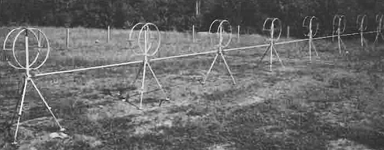
Fig. 1 - Typical aperiodic loop antenna array has 36 elements in 50-meter circle. An electronically steerable antenna has an important advantage over other antenna types; it can pinpoint its beam at a single target. Steerability and high performance are features of a truly unique antenna design developed by E.M.I.-Cossor Electronics Ltd. This aperiodic loop antenna is a high-gain steerable system designed to provide the maximum directive gain in the smallest possible amount of space. The basic beam pattern is optimized for the reception of high-frequency signals (2 MHz to 32 MHz) propagated via the ionosphere, in the same manner as the aperiodic linear arrays.
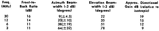
Table 1 - Directional characteristics of aperiodic loop antennas. The antenna consists of 36 loop elements arranged around the perimeter of a 150-foot circle. By appropriate phase shifts, the loop outputs are combined to provide simultaneous beams every 10 through 360 degrees. Alternatively, with a commutator switch, the beam can be made to scan at a fixed rate. This latter capability is especially valuable when the antenna system is used as a direction finder, while the former arrangement provides directional gain characteristics equivalent to 18 rhombic antennas inclined at 10° to one another. The basic antenna element is an untuned balanced loop whose dimensions are small compared to the wavelength. A transistorized preamplifier, fitted at the antenna base, exactly complements the loop characteristics. This combination results in a constant effective height over the full four-octave frequency range, that is, the preamplifier output voltage (at a constant 50-ohm impedance) is constant over the complete frequency range for fixed incident field strength. Because of the flat frequency response, the antenna has a well-defined phase characteristic and is, therefore, particularly suited for a phased antenna system. The aperiodic configuration comprises loop/preamplifier elements in an "end fire" array with interconnecting transmission lines coupling each element. Outputs are available at both ends so that the array can look both ways simultaneously if required or can be switched rapidly through 180° with a coaxial relay.
Several government agencies mid institutions have begun to use aperiodic loop antennas as part of their national and international communications systems. The array is being used by Diplomatic Wireless Service in Buckingham, England; Department of Transport, Ottawa, Canada; U.S. Navy; and University of Denver. <---- Technological prescience refers to the rare ability to accurately foresee or anticipate future technological developments, inventions, or trends well in advance of their realization. It combines deep technical insight, pattern recognition from historical precedents, and intuitive leaps about scientific trajectories. In practice, it's undervalued today amid hype cycles (e.g., metaverse flops vs. steady AI progress). True prescience demands skepticism of short-term trends and focus on exponential laws like computing power doubling. Few possess it; most "futurists" recycle buzzwords. |
|||||||||||||
 |
|||||||||||||
|
|||||||||||||

|
||||||||||||||||||||||||||||||||||||


