|
May 1967 Electronics World
 Table
of Contents
Wax nostalgic about and learn from the history of early electronics. See articles
from
Electronics World, published May 1959
- December 1971. All copyrights hereby acknowledged.
|
This article from the May 1967
edition of Electronics World shows you just how long the
Frequency Electronics company
has been around! In fact, here is an excerpt from their website: "Frequency Electronics,
Inc. was founded in 1962 and is now a well-established public company in Long Island,
New York, and trades on the NASDAQ Stock Exchange under the symbol FEIM." Mr. Irwin
Math, the project engineer at Frequency electronics who wrote the article, has surely retired by now. The discussion on short-
and long-term stability is as relevant today as it was 45 years ago.
Interestingly, the term "phase noise" is nowhere to be found. Neither is
"digital," which might explain the absence of the former.
Selecting Frequency and Time Standards


Fig. 1 - Measuring long-term stability by means of peak readings.
By Irwin Math / Project Engineer, Frequency Electronics, Inc.
How precision oscillators and clocks are rated and exactly what they are capable
of. A discussion of stability and other important standard specifications.
Highly precise frequency and time standards are becoming more and more widely
used in today's sophisticated scientific world. The missile and space age demands,
for example, are far in excess of the requirements of only a few years ago. In fact,
the stability of the research laboratory's frequency standard of 10 years ago is
now taken for granted in the oscillators of many types of modern industrial test
equipment.
As a result, all too often the engineer or technician will specify a complex,
ultra-stable frequency standard when a much less stable one would have been sufficient
for his application. Similarly, he can often mistakenly interpret a lower order
oscillator as easily as one of much higher quality. For these reasons, the engineer
and technician as well as anyone with even a casual interest in the measurement
field should have a good of just how precision oscillators and clocks are rated
and exactly what they are capable of doing.
Long-Term and Short-Term Stability
In the "good old days", it was enough to ask for a 1-MHz oscillator with a stability
of ±0.001%. Anything better than 0.1% was considered rather good. But today things
have changed. All but the simplest of oscillators that are used as standards are
rated in parts per 10". For example, a 1-MHz oscillator with a stability of ± 1
Hz is rated at 1 MHz ±1 part in 106 or 1 part per million. Similarly,
a good frequency standard may have a stability of ±1 part in 1010
The general expression for frequency stability is S=ΔF/F where F is the nominal
frequency and ΔF is the allowable variation. Therefore, the actual frequency variation
of our frequency standard (considering its output is 1 MHz nominal) is ±0.0001 Hz
or ±1 x 10⁻¹⁰ of the nominal frequency.


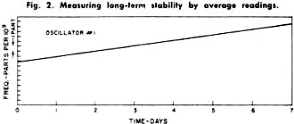
Fig. 2 - Measuring long-term stability by average readings.

Fig. 3 - Automatic recording of an oscillator with a short-term
stability of plus or minus 5 parts in 109 per second.

Fig. 4 - A typical high-quality frequency standard which has
a long-term stability of plus or minus 1 part in 1010.


Fig. 5 - Test setup employed for short-term measurements.

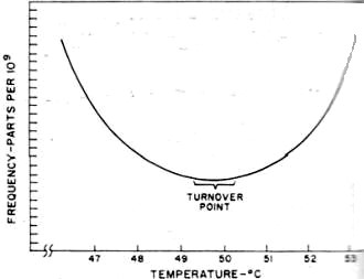
Fig. 7 - Typical frequency vs. temperature characteristic for
a high-quality crystal. Oven is set to "turnover-point" temperature.
However, this information is not enough. While it does indicate stability, it
does not specify over what period of time this stability must be measured, The complete
stability of a frequency-standard oscillator must be given in two parts: the long
term and the short term.
The long-term stability of an oscillator is basically the average change in frequency
over a long fixed period of time as compared to some absolute reference. Usually,
long-term stability is measured in one of two ways. The first of these, as indicated
in Fig. 1, depends on readings of frequency taken continuously for several days.
The maximum peak-to-peak deviation over any 24-hour period is measured and the stability
is then defined as ± one-half this maximum. For example, since both oscillators
in Fig. 1 have a peak-to-peak variation of 1 part in 108 per day, their
long-term stability would be specified as ±5 parts per 109 per day. Notice,
though, that oscillator #2 has a much longer average rate of frequency change than
does oscillator # 1. Therefore, while they both are ±5 parts in 109 per
day oscillators, oscillator #2 is obviously superior.
The second method, and by far the more accurate one, is based on the average
change of frequency over a given time interval. As shown in Fig. 2, the stability
of oscillators #1 and #2 is now determined by the slope of their average frequencies.
Now it is easy to see that oscillator #2 is substantially better than oscillator
#1.
To further clarify the measurement and eliminate any remaining doubt, a few oscillator
manufacturers incorporate both the average long-term frequency change and the day-to-day
change in their long-term stability specification. For example, a 1-MHz oscillator
such as the one shown in Fig. 4 with a rated long-term stability of ±1 part in 1010
is one whose maximum daily and average frequency will change by no more than ±1
cycle per 10 billion cycles per day or 0.0001 cycle per day.
The short-term stability of an oscillator is its frequency stability over periods
of time from a few seconds to fractions of a second. This type of specification
is important when the oscillator is used as the source for a frequency multiplication
system, especially into the thousands of MHz. If, for example, a 1-MHz oscillator
with a second-to-second variation of ±1 part in 106 were multiplied to
1000 MHz, the variation would now be ±1000 Hz per second.
As in long-term measurements, there are two general methods. One is similar to
long term in that readings of frequency are taken. The time interval, however, is
much shorter. Fig. 3 is a recording of an oscillator with a short-term variation
of ±5 parts in 109 per second. Notice that in any 1-second interval,
the frequency never deviates by ±5 parts in 109 from the nominal. This
type of recording is used for intervals as low as 0.1 second. Smaller intervals
require too fast a recorder speed and are measured by the second method.
This method involves a statistical approach. The oscillator to be measured is
fed to a low-noise mixer along with a very stable reference frequency.
The difference of the two signals is then fed to a counter which measures the
period (or wavelength) of this signal. A typical setup is shown in Fig. 5. The difference
frequency actually triggers a gate, allowing a very stable 10-MHz signal to drive
the counter. Since the period of the difference signal determines how many cycles
of 10 MHz will be fed into the counter, great accuracy can be achieved. Assuming
that the difference signal is 1 Hz, this means that 10,000,000 cycles will pass
into the counter through the gate for each cycle of input. Therefore, only 1/10,000,000
of a second change in the difference signal will cause the counter to indicate a
change. Since such great resolution is possible by this technique, extremely short
intervals of time can be measured and interpreted as short-term stabilities.
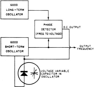
Usually an oscillator with good short-term stability will not exhibit a good
long-term characteristic and vice versa. As a result, where both long- and short-term
stability must be as good as possible, the technique shown in Fig. 6 is used. A
very good long-term standard and a very good short-term standard are fed to a phase
detector. The d.c. output of the phase detector is then fed back to a voltage-variable
capacitor in the short-term standard which causes its frequency to "lock" to the
frequency of the long-term unit. This "phase-locking" technique now produces an
output with excellent long- and short-term stabilities.

Fig. 6 - A phase-locked oscillator system is illustrated.
The stability of an oscillator with changes in ambient operating temperature
is another important factor to consider when specifying high-stability oscillators.
Fig. 7 is a curve of the temperature versus frequency characteristics of a typical
high-quality crystal. It can be seen that changes in crystal temperature result
in significant changes in frequency.
It is therefore extremely important to isolate the crystal from the effects of
varying temperatures. Vacuum bottles (dewars) are often employed in the highest
stability units and, in most cases, the crystal itself is in a well-regulated, temperature-controlled
oven.
Similarly, changes in operating voltage, line voltages, and load impedances are
all important and should be considered when choosing oscillators. The effects of
these parameters are stated in terms of the maximum frequency changes they produce
in the oscillators' output.
Other Important Criteria
Some of the other more important criteria which should be considered when selecting
equipment of this nature are:
1. Construction - the equipment should be able to withstand mechanical shock
and also occupy the least amount of space, especially where it is to be part of
a physically complex system.
2. Power consumption - in portable, airborne, or other such applications, it
is desirable to obtain the lowest power consumption of the oscillators in order
to realize the longest usable life. 3. Measurements should be the result of exhaustive tests on many units of the
type to be used, where possible.
Finally, perhaps the most important "specification" to many technical personnel
is cost. While mechanical construction and ambient temperature isolation will determine
the cost of a unit to an extent, the primary cost factor is the ultimate stability
of the unit. The greater the stability required (both long- and short-term) the
more elaborate the circuitry required and better the crystal must be. For example,
while a ±1 part in 108 oscillator is available for $200, a ±1 part in
1010 oscillator can easily cost $2000.
|


