|
|||||||||||||
 |
|||||||||||||
How to Select R.F. Chokes
|
|||||||||||||
Wirewound inductors (as most are) can be mysterious entities even when you are familiar with their many interdependent physical and electrical properties. Because of interwinding capacitance and a sometimes (when a large number of turns are involved) rather significant series resistance, the equivalent circuit model gets quite complex - literally in a mathematical sense. If you have the luxury of staying far away from the self-resonant frequency (SRF) of the coil, your component will behave very much like an ideal inductor, that is, XL = 2πfL. This 1966 Electronics World magazine article delves into what causes inductors to act like parallel and/or series resonant tank circuits, how to avoid the inconvenience of unwanted resonances, and how to exploit resonances in your favor. You'll also learn (if you don't already know) the distinction between a "choke" and an inductor. How to Select R.F. Chokes
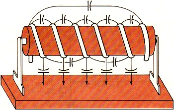
Fig. 1 - Besides inductance, on RFC, like any other coil has some distributed capacitance between turns and to chassis. By Joseph Tartas There is more to an r.f. choke than some wire wound about a form. When all its characteristics are known, it can prove useful as a tuned circuit, transformer, low-or high-pass filter, as well as an r.f. isolator. Not so many years ago, the selection of an r.f. choke was not a difficult problem. You simply asked for a Z-50, if you were working in the 50-MHz area, or a Z-14 if your circuitry was in the 10- to 15-MHz range. Chances were, you didn't know anything about the choke itself, other than taking the manufacturer's word that it was designed to work in that range. For very-low-frequency work, the selection of a choke usually depended more on the inductive reactance and hence was usually some arbitrarily selected value of high inductance. If you were really designing, you might make a lot of calculations and measurements, throw in a few rules of thumb, and come up with the right value. Today, the picture has changed considerably and instead of two or three makes of chokes and a dozen or so values to select from, there are hundreds of sizes and shapes as well as specific characteristics to meet extreme temperature, moisture, or other environmental requirements. In a single manufacturer's line, there are several physical sizes designed to fit requirements of current-carrying capabilities and space limitations; and in cases of extremely small volume, there are non-insulated chokes to reduce the physical size but retain the same electrical characteristics.
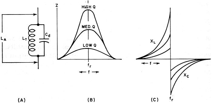
Fig. 2 - (A) How an RFC looks electrically. (B) and (C) show "Q" and reactance, respectively, for different values of "Q." The most important improvement in the RFC field in the past few years is the information made available to the user through manufacturers' literature. This information includes inductance; minimum "Q" (although often misleading-this will be discussed farther on); approximate resonant frequency, perhaps the most important item; the approximate distributed capacitance; the minimum parallel resistance at two widely separated frequencies; the maximum d.c. resistance; the maximum current rating; and in the case of one manufacturer, incremental current rating. Because of extreme environmental requirements in military and industrial equipment these days, many chokes are also rated for maximum temperatures ranging from 85° to 500°C and power dissipations that depend upon body sizes, covering materials and core materials. In spite of all this information, it often requires a bit of reading between the lines before you can make a sensible selection of the correct RFC to use in your particular circuit. Before you can do this, however, you must have a thorough understanding of the various characteristics and circuit requirements that go into such a selection. Why a Choke Is Used Basically, an r.f. choke is nothing more than an inductance that, because of its own distributed capacitance, forms a parallel-resonant circuit. This distributed capacitance (Fig. 1) is a multiplicity of small capacitances existing between adjacent turns and from anyone turn to all the others, as well as to a shield if one is used, and to a ground if one exists in the vicinity of the choke when it is installed in the equipment. For the moment, consider the self-capacitance, or distributed capacitance itself (without the choke-to-ground capacitance), as being in parallel with the pure inductance of the coil and having a resistance equivalent to the resistive component of the choke. A choke would then appear schematically as in Fig. 2A, and its impedance and reactance as in Figs. 2B and 2C, respectively. As in all parallel-resonant circuits, the maximum impedance at resonance will depend upon the "Q" and this, in turn, will be the deciding factor as to how effective the choke will be at its self-resonant frequency and over how wide a frequency range it will still be effective. The impedance depends upon the amount of self-capacitance that exists in the choke and the equivalent parallel resistance. A good approximation of the impedance of a parallel-resonant circuit is Zr = L/CR as long as the circuit "Q" is at least 10. The value of R is normally the sum of the series resistances of the inductance and capacitance, but in a choke the resistance involved in the distributed capacitance is practically non-existent. This, then, boils down to the inductance, the distributed capacitance, and the resistance of the winding (d.c. + r.f. resistance as frequency goes higher) as affecting the over-all performance of the choke; that is, the resonant impedance, the self-resonant frequency, the "Q" and hence the bandwidth of the choke, and its effectiveness on the r.f. voltages it is being used to suppress. Thus, it is obvious that the value of inductance of a choke is not as important as the self-resonant frequency and impedance, although the inductance does have some bearing on these factors. Chokes come in many forms, the particular type depending upon the frequency involved, the inductance necessary to achieve it, and the distributed capacitance that results from the particular form factor and winding method. Many are simple single-layer solenoids with or without powdered-iron cores; others are multi-layer coils of various configurations; still others are single or multiple honeycomb windings with one or more sections combined in series. A single-layer solenoid has the lowest distributed capacitance, and this capacitance is proportional to the diameter of the winding and to a smaller degree is affected by the length and number of turns and, where only a few turns are involved, the spacing between turns. For a single-layer, close-wound choke, the distributed capacitance is approximated by Cd =.75 diameter (in inches), with C in pF.
Fig. 3 - Two different methods of winding multi-turn coils. Note winding arrangement difference between (A) and (B).
Fig. 4 - Styles of coil construction. (A) Method of winding a slot-wound coil. (B) A winding form as used for slot-wound coils. (C) Self-supporting coil. In a multi-layer coil (Fig. 3A), the capacitance is considerably greater, not only because of the greater number of turns but also because of the relative capacitances between layers and nearby turns. If the layers are wound so that the difference of potential between any two adjacent turns is small, then the capacitance is small; if the layers are wound in such a way as to have adjacent turns non-parallel to each other, as in the honeycomb or universal winding, the capacitance is at a minimum between those adjacent turns. The total distributed capacitance may be further reduced by the use of powdered-iron or ferrite cores which reduce the number of turns of wire necessary to obtain the desired inductance value. However, other problems enter when cores are used, since the core losses, the capacitance effects due to the dielectric material used in making the cores, and the useful temperature range and effective permeability of the core which affect the "Q" must be considered, as well as a factor that is often ignored in r.f. chokes, the temperature coefficient of the core, which also affects the temperature coefficient of the choke. In multi-section chokes, the individual sections may be alike or may be designed so that the over-all choke appears as a broadband filter. In most cases, the choke is not like a single resonant circuit but appears electrically as a multi-element bandpass filter. When a large inductance is required and the use of a single-layer coil is prohibitive because of its size, the multi-layer coil becomes necessary. This, in turn, means a larger distributed capacitance which is no longer directly related to the diameter or coil size. One method of reducing capacitance is to wind the coil in such a way that the high-numbered turns do not lie next to low-numbered turns (the condition for greatest capacitance). Early attempts to reduce capacitance by means of "bank-winding" (Fig. 3B) resulted in expensive chokes, since this method required great skill by the winder and it could not be done by machine. The coil could not be held to the production tolerances then required (and completely unusable with today's close-tolerance requirements), and when large inductances were needed, the coil was so large physically as to be almost impractical. The development of the universal coil winder provided the designer with a new and extremely useful tool that allowed him to repeatedly produce a mechanically stable, relatively low capacitance coil with a fairly large inductance. This type of winding, while not having the lowest attainable capacitance, was better than a "happy medium" between the excessive capacitance of the layer-wound and the great expense of the bank-wound coil. The "universal" layer-wound coil, more commonly known as "pie-wound" because of its resemblance to a pie, is a compromise between the bank-wound coil of Fig. 3B and the slot-wound coil of Fig. 4A. The slot-wound coil has a distributed capacitance equal to a two-plate capacitor, each plate consisting of rings the width of the slot with one plate having the inner coil diameter A (see Fig. 4B) and the other plate the outer diameter B. Since a two-plate capacitor of two greatly different areas depends to a large extent on the area of the smaller plate, the smaller the diameter of the inside ring (or the winding form in this case) the smaller the distributed capacitance, and conversely, the greater the inductance the pie will have for a given width and outer diameter. The universal-wound pie of Fig. 4C is simply a free-standing, self-supporting, slot-wound coil with a winding similar to the bank-wound coil, although restricted because of the narrow cross-section of the slot. As the art progressed, powdered-iron cores were developed, and their use as forms or cores for universal-wound r.f. chokes allowed a great reduction in over-all size. Like all new materials, powdered iron had its own limitations. If the permeability (μ, the ratio of inductance with the core, to the inductance without the core) was low, and the losses resulting from the insertion of the core in the coil (eddy losses) were kept to a minimum (resulting in a reasonably high "Q"), the size of the coil was not reduced greatly. Increasing the μ of the core material reduced the choke size, but often it was found that the "Q" suffered greatly due to core losses so that the series impedance (QX) was inadequate to warrant the use of a costly and bulky component. Eventually, new ferrite materials (ceramic materials with magnetic qualities) were developed which allowed for great reduction in the size of an r.f. choke, but as environmental temperature specifications for equipment were raised above the usual 85°C, the temperature capabilities of the ferrites fell apart. Either the temperature coefficient was poor, causing excessive change in effective inductance with change in environmental temperature, or the permeability decreased so rapidly above 85°C that the resulting inductance became too low to be effective long before the maximum temperature requirements were met. This led to further improvements in the capabilities of ferrite core materials, and we now have extremely large inductances in very tiny packages with excellent temperature and mechanical stability, and because of the extremely high permeability of the cores, the distributed capacitance or "self-capacitance" of the choke remains quite low. Examples of this size reduction are a miniature 1000-μH choke with a molded phenolic form having a distributed capacitance of 5 to 10 pF for several makes, and a ferrite-bodied choke with the same effective inductance yet having less than I-pF capacitance. Chokes having an iron core, for the same inductance, run somewhere in between, with a maximum capacitance of 7 pF. In large chokes using non-miniature techniques, the capacitance is usually not given, and often the self-resonant frequency is ignored as well. Because these chokes are usually wound with larger wire to accommodate high currents, the capacitance of these chokes would be even higher than that of the miniature types.
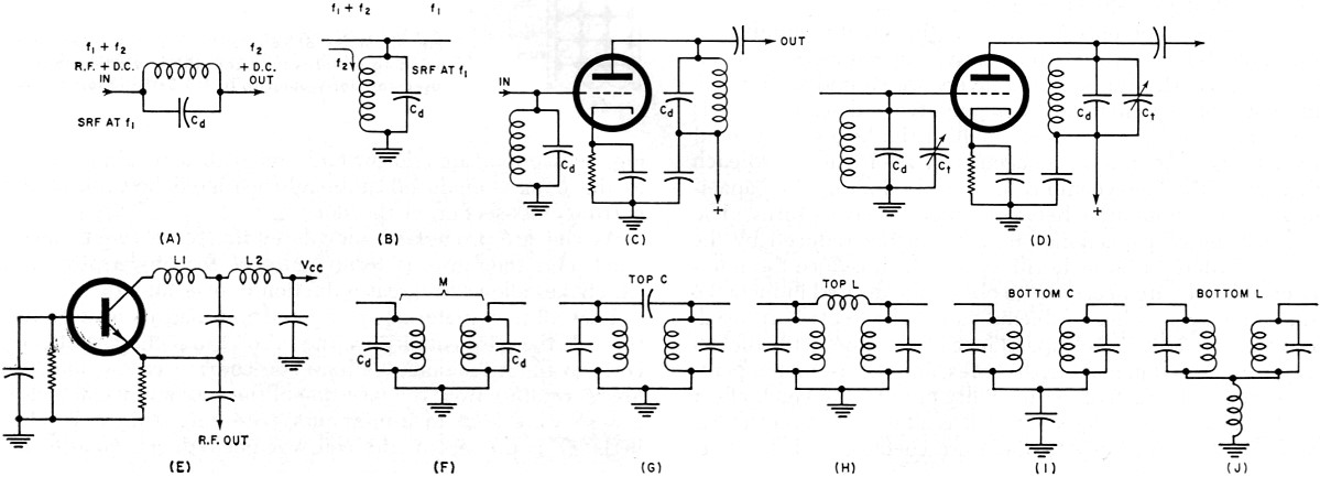
Fig. 5 - De-rating curve for one type of miniature r.f. choke. The current rating of a choke will often depend upon the ambient temperature and will have to be derated. Fig. 5 shows a curve for de-rating one type of miniature choke. If the current rating is given at the maximum temperature to be encountered, then only the incremental current is of interest. This is the current necessary to reduce the effective choke inductance by 5% due to the magnetization of the iron core that effectively lowers the permeability and hence the inductance. Chokes are normally used to prevent coupling of r.f. power (microwatts or megawatts) from one circuit to another in a piece of equipment. Any wires that lead from stage to stage, circuit to circuit, or from one sub-unit to another are potential conductors of undesired r.f. In r.f. circuitry in particular, there is usually a series of cascaded amplifier or multiplier stages, and more often than not, an oscillator or two. Furthermore, mixers, detectors, and other associated circuits are commonly involved in such circuitry, and each is a source or terminus for leads that might conduct unwanted r.f. These leads can be any or all of the following: "B+," "B-," a.g.c., filament leads, fixed bias leads, leads to panel controls, and video or audio input and output. Carefully selected, the proper choke can be an r.f, isolator; a shunt trap; a tuned circuit either at its self-resonant frequency or, by means of additional shunt capacitance, at some lower frequency; or can be combined with other components to make a low-pass, high-pass, or bandpass filter. A recently introduced innovation is a series-resonant trap that is in appearance an r.f. choke. Utilizing the capacitance between turns as a series-coupling element, it can be made in a wide range of series self-resonant frequencies. Like the parallel-resonant choke, the series trap will probably find applications that formerly required an external capacitor in conjunction with an RFC to make a series-resonant trap. How to Use Chokes Because a choke is composed largely of distributed inductance and capacitance rather than lumped inductance and capacitance, it appears electrically as a transmission line rather than as a tuned circuit. Depending upon the values of these constants and the terminating impedance of this transmission line, a choke can act as an impedance varying from extremely high to almost a perfect short. At the fundamental (self-resonant) frequency and at all odd multiples of this frequency, a choke appears as a parallel-resonant circuit. At even multiples, the same choke acts as a series-resonant circuit with the lowest impedance limited only by the series-resonant resistance, or essentially the resistance of the coil itself. This phenomenon occurs because a choke does act as a transmission line and is not terminated in its characteristic impedance. If it were so terminated, a choke would be little more than a straight conductor or loss less transmission line for the r.f. currents. Because of the distributed elements, a choke may be thought of as a series circuit composed of a number of elements, each element consisting of several small inductances and capacitances in parallel; as two parallel branches, with one leg a series of small coils and the other leg a series of small capacitors; or even as a combination of the two, which would make it the equivalent of multi-element filter circuits. Hence, at any given frequency, a choke can appear as almost anything from a high parallel-resonant impedance to a very low series-resonant impedance. It is customary, however, to select a choke having its highest parallel-resonant impedance when it is to be used as an r.f. suppression element in a supply line (in series with a "B+" line, for example), as shown in Fig. 6A. If a choke is selected having the same self-resonant frequency (SRF) as the frequency it is desired to suppress, then the choke must have the highest series impedance at that frequency. And because a choke is a completely self-contained high-impedance element, its SRF is not affected by external elements connected from either end to ground, and further attenuation is achieved by bypassing either or both ends of the choke. It is, however, affected by any parallel elements, and hence its SRF, "Q," or parallel-resonant impedance can be lowered.
Fig. 6 - Various uses for r.f. chokes. (A) R.f. suppressor. (B), (C), (D)Used as a tank coil. (E) Tuned circuit with tap. As a transformer, an RFC can be used with (F) mutual, (G) top C, (H) top L, (I) bottom C, (J) bottom L coupling.
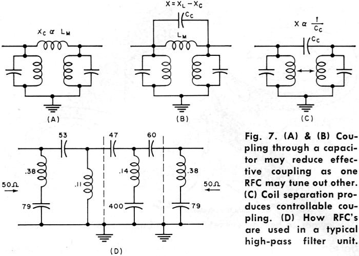
Fig. 7 - (A) & (B) Coupling through a capacitor may reduce effective coupling as one RFC may tune out other. (C) Coil separation produces controllable coupling. (D) How RFC's are used in a typical high-pass filter unit. Because it can be altered, such a choke may be utilized as a tank coil and tuned by a fixed or variable capacitor connected across the choke (Figs. 6B, 6C, and 6D) and have its loaded "Q" adjusted by adding a parallel resistor (or tube or transistor circuit). Two chokes in series, with the combination shunted by a capacitor, provides a tuned circuit with a tap (or an autotransformer), as shown in Fig. 6E. The tap can be adjusted by the proper selection of the inductance ratio or impedance ratio desired. Because of the extremely wide range of available chokes (0.10 μH to many millihenrys) in small increments, almost any ratio is obtainable. It is also possible to use two chokes as primary and secondary of a transformer (Fig. 6F). Again, the wide range of values can be utilized for almost any transformation ratio. Depending upon the size and type selected (magnetically shielded types would not be suitable), the degree of coupling can be varied over a considerable range by adjusting the relative separation between the two choke bodies. If greater coupling is desired than can be obtained by mutual coupling, the usual methods of top C, top L, bottom C, or bottom L, as shown in Figs. 6F through 6J, can be utilized. However, because of the mutual inductance that exists between two chokes in close proximity to each other, additional coupling through a physical capacitance may actually reduce the effective coupling because one effectively tunes out the other (Figs. 7A and 7B). To prevent this from occurring, sufficient separation to minimize mutual coupling will give better control through the coupling elements, as indicated by Fig. 7C. It is just this capability of being coupled to a coil or another choke that often requires that a choke be connected so that such coupling is at a minimum. Contrary to the usual v.h.f. and u.h.f. wiring practices, it is often necessary to use maximum lead lengths on chokes so that they may be placed away from tuned circuits or supply lines containing similar or different chokes. And because of the peculiarities of the distributed constants that make the choke what it is, the extra lead length has little effect on its performance. Furthermore, placing a choke near the chassis, although increasing the effective distributed capacitance somewhat, will provide a certain degree of shielding. If the choke is magnetically shielded, so much the better, for such a choke will not only have little or no coupling to circuits but will also not radiate any r.f. to surrounding circuits as is possible with unshielded chokes. However, a note of caution is necessary. If a magnetically shielded coil is placed too close to a tuned circuit, it can effectively load, or lower, the "Q" of that circuit considerably because the closed ferrite body of the choke acts as if a shorted turn were coupled to it. As a series element, a choke may also be used as a trap, either at its SRF or at some other frequency, by tuning it as a parallel circuit with additional capacitance. As such, it may be coupled to a circuit either magnetically or capacitively. As a series-tuned trap, the tuning capacitance should be large relative to the distributed capacitance of the choke so that the effect of the distributed capacitance is minimized. If the choke inductance is small, its effective inductance may be adjusted by the length of its leads, as much as 10%. Chokes may also be used, because of the small physical sizes and wide range of inductances available, in the construction of miniature filters. A typical high-pass filter is shown in Fig. 7D. In a majority of cases, the capacitance required is large, the inductance values small, and the mutual coupling must be at a minimum. Magnetically shielded microminiature chokes, combined with miniature ceramic capacitors, can produce a high-pass, low-pass, or bandpass filter of incredibly small size yet with extremely sharp bandpass characteristics and large off-frequency attenuations. Reliability R.f. chokes, like all other components, must be selected with a bit of wisdom and a lot of understanding. In general, most standard makes of chokes will give satisfactory results even beyond their rated capabilities, although this is not a recommendation to use them in that way. As long as chokes are operated within their intended ratings, and their specifications and intended applications are considered wisely, there should be no problems either in experimental use or in production. Recent impartial tests indicate that potted, cement-coated, or otherwise encapsulated coils tend to have a higher rate of failure as wire diameter is decreased. Encapsulation tends to restrict the thermal expansion of the windings due to the different expansion rate of the encapsulating material. These tests indicate that such a restriction causes the wires to bite through the insulating coating and short adjacent turns together. However, these tests also show that the failure rate only increases rapidly above #34 AWG and at temperatures in excess of 150°C. Furthermore, most encapsulated chokes use materials that do not hinder expansion of the windings since the materials are, to a wide degree, either compatible in expansion coefficients or are thermosetting and tend to soften slightly with elevated heat. How to Measure Any of several instruments may be used to determine the various characteristics of r.f. chokes. The necessity for doing so, however, will depend upon what kind of information is made available by the manufacturer and just what interpretation can be made of this information. The approximate SRF (self-resonant frequency) may be found quite simply with a grid-dip oscillator, provided the choke is not completely magnetically shielded. If more than one dip is observed, the lowest frequency indicated will be the fundamental SRF. With this set-up, you can then alter this frequency with additional shunt capacitance, meanwhile monitoring the change until the desired frequency has been reached.
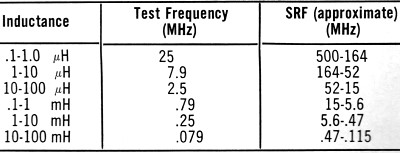
Table 1 - Self-resonant frequency is higher than test frequency.
Table 2 - The relationship between choke and "Q" meter tuning. For any type of choke, shielded or not, a "Q" meter can be used to determine the SRF and, simultaneously, the distributed capacitance and the "Q" at the SRF. This last point is often overlooked in the application of a choke and the use of the available data. A careless reading will lead the user to believe that the "Q" shown is at the SRF, when it is actually the "Q" that is obtained at the frequency of measurement at which the inductance measurement is made on the "Q" meter. Only at the given test frequency does the "Inductance" dial read correctly, but the test frequencies for the various inductance ranges differ from the SRF by a factor of 2 to 20 in the normal range of miniature choke values. The differences for one make of choke are shown in Table 1. It is obvious from this table and from the vast differences in "Q" for the same coil at various frequencies that one measurement cannot substitute for the other. Of course, the "Q" may not be important in many applications, but where it plays a significant part, it must be determined for the SRF or the frequency at which it is to be used. The SRF is measured on the "Q" meter by the following procedure. Connect the test leads to the "Cap" terminals. With the choke disconnected and the leads in place, connect to the "Coil" terminals a relatively high "Q" work coil that will resonate in the region of the expected SRF of the choke. The choke is then connected to the test leads on the "Cap" terminals and the "Capacitance" dial is tuned to re-resonate the combination. If no change is necessary, then that frequency is the SRF of the choke. If the "Capacitance" dial must be shifted to re-resonate, then the entire procedure must be repeated, but at a higher or lower frequency until the SRF is found. As a guide, Table 2 shows the relationships among the various indications. The effective parallel resistance Rp and effective parallel reactance Xp at any frequency may be found by a similar method, except that the process used to pinpoint the SRF is not necessary. Adjust the "Q" meter for resonance at the test frequency F and record the indicated "Q" as Q1 and capacitance as C1. Remove the test leads from the "Cap" terminals and record the increase in capacitance needed to re-resonate the "Q" meter as C2. Reconnect the leads and the choke to be measured, and re-resonate at F. Call the new reading Q2. The effective parallel resistance is found from Rp = [(1.59 x 10⁵)
(Q1Q2)] / [f (C1 + CL) (Q1 - Q2)] and the effective parallel reactance is found
from Xp = (1.5 x 10⁵) / f (C2 - C1) where f is in MHz and
C is in pF. The impedance is Under some conditions (C2 - C1) may be negative, indicating a capacitive reactance for the choke at that frequency. The "Q" is found from "Q" = [ (C2 - C1) (Q1Q2)] / [C1 (Q1-Q2)] and is the "Q" of the unknown impedance, or in this case the choke being tested. This is obtained from the relation "Q" = Rp/Xp. The distributed capacitance may be measured with the "Q" meter by the two-measurement method when the distributed capacitance, Cd, is 10 pF or less, as follows. Connect the choke to the "Coil" terminals and resonate the choke by varying the "Frequency" dial, with the capacitance set at a low value (30 to 50 pF). Note the frequency and call this capacitance C1. Change the frequency setting to one-half the previous frequency setting and re-resonate the coil by varying the "Capacitance" dial. The new value is called C2. The distributed capacitance, within 20%, is found by Cd = (C2-4C1) /3. A much simpler method of determining the approximate value of Cd is from a resonance chart, where frequency, inductance, and capacitance are shown. As long as Cd is small, it has a negligible effect on all but very small values of inductance. For this reason, the apparent inductance will be close to the true inductance, and the chart would probably show the required capacitance to resonate the apparent inductance with as good an accuracy as the "Q" meter. For example, a 10-μH ±10% choke measured by the above method had an apparent inductance of 10.7 μH and a distributed capacitance of 0.67 pF. The "Q" at SRF was not measured because the SRF was above the range of the "Q" meter. From a resonance chart, the apparent inductance given in the manufacturer's data sheet gives a capacitance value slightly higher. The actual inductance that would be measured if the choke had no distributed capacitance at all is found from the value obtained in the Cd measurement. The true inductance is LT = LA [1[C1 / (C1 + Cd)]. In the case of the 10-μH choke just mentioned, LT = 10.7 [38/(38+.67)] = 9.83 μH where C1 is the capacitance required to measure the apparent inductance, 38 pF in this case; and LA is the apparent inductance. Thus, the SRF can be determined from the values of LT and Cd, or the approximate Cd can be obtained from the approximate SRF and a resonance chart. Because of the nature of r.f. chokes and their various circuit requirements, these approximations will quite often be adequate. |
|||||||||||||
 |
|||||||||||||
|
|||||||||||||


 at any frequency, and
Z = Rp at the SRF since Xp = 0 and
at any frequency, and
Z = Rp at the SRF since Xp = 0 and  .
.
|
||||||||||||||||||||||||||||||||||||


