|
|||||||||||||
 |
|||||||||||||
R. F. Interference Filters
|
|||||||||||||
Sprague Electric engineer Benedict Rosen, discusses how the characteristics of a circuit in need of protection against RF interference needs to be considered when selecting filter components. He points out that attempting to hang a shunt feedthrough capacitor on the input and/or output of a low impedance (e.g., 50 Ω) RF circuit could make the situation worse, depending on whether the circuit is strongly capacitive or inductive in its out-of-band region. Sprague was a major manufacturer of all sorts of capacitors qualified for use in military and aerospace systems, so they put a lot of effort into characterizing device parameters over a wide range of voltage, current, power, temperature, mechanical, and frequency environments. R. F. Interference Filters
The author is an electrical engineering graduate of the Massachusetts Institute of Technology and a member of the Institute of Electrical and Electronics Engineers. He also serves as Chairman of Committee P.3.6 on electric wave fillers of the Electronic Industries Association. By Benedict Rosen / Asst. Manager, Filter Div., Sprague Electric Co. Modern electronic devices with low power levels and high sensitivities require improved EMI filters. The challenge for the filter designer is to develop smaller components and to improve packaging techniques. Almost every new electronic device demands a place in the frequency spectrum free from interference of all others. And, the great majority of these new components are more sensitive to "noise" than their predecessors. In many cases, electromagnetic interference (EMI) filters are called upon to protect complex systems, such as missiles and computers as well as simple electronic devices, from performance degradation due to outside electromagnetic interference and to keep unwanted radiation "inside" away from other sensitive circuits.
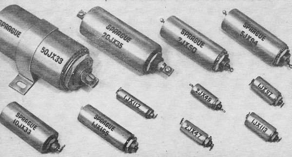
In general, most of the smallest and lightest interference control filters used in military and industrial electronic and electric equipment are packaged in cylindrical-shaped cans. This design uses to advantage the natural shape of the rolled capacitor sections and the toroidal inductors which form the filter. In addition, the design facilitates mounting the units on panels, or with threaded necks, on bulkheads. The feedthrough characteristics of this class of component enhances filter effectiveness by eliminating mutual coupling between input, or noise source, and the output terminals. Filters are available in an almost infinite variety of shapes and sizes. Extremely large power-line filters are used in shielded rooms to protect communications equipment from transients. On the other hand, subminiature filters have become commonplace. These tiny devices are able to fit into the head of a multi-pin connector with 50 or more of the units requiring less than one square inch of space. In both filter types, all kinds of capacitors - paper, film, electrolytic, and ceramic - and inductive elements - ferrites, powdered iron, etc. - are utilized in the construction. The selection of the proper capacitor-inductor unit is, of course, entirely dependent on the intended application. A small ceramic feedthrough device may cost as little as 50 cents; the price of some high-current power-line filters runs as high as $1000. A typical single-line, 1-to-5-ampere, 200-V d.c. or 117-V a.c. filter sells for $2 to $10 in large quantities. These are generally manufactured in a cylindrical configuration and are by far the most widely used EMI filters. Size is pretty much a function of both current and voltage - increasing with thicker dielectrics for higher voltage ratings and larger core volumes for higher currents. Stability "Most filters which use film capacitors are relatively stable with voltage, and temperature. However, insertion loss varies with frequency and current. Current instability is due almost entirely to the change in permeability of the core material with saturation. This phenomenon is well known and is exhibited, to some degree, by all inductors which use magnetic material. Frequency instability, on the other hand, is a result of changes in component impedances with frequency and other distributed parameters. An "L" circuit filter, for example, will generally have dips in its insertion loss curve somewhere between 1 and 100 MHz, depending on the resonant frequency of the coil.
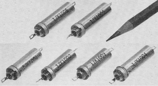
Some typical subminiature electromagnetic interference filters. Low-pass filters like these are used on low-voltage power and control lines where the low impedance of the power source must be maintained. Many manufacturers have found that their small size, light weight, and high performance are particularly suited for use in high-density packaging applications. Temperature and voltage stability have become significant additional considerations with the newest line of interference filters - those containing ceramic capacitors and ferrite inductors. Both ceramics and ferrites are susceptible to temperature fluctuations. In addition, the ceramic capacitor is the first shunt element used in EMI filters which exhibits a substantial voltage instability. This characteristic presents a potentially serious problem since some widely used components show variations in insertion loss of as much as 15 to 20 dB over the specified operating voltage and temperature range. Impedance Typically, interference filters are measured in a system where both the input and output impedances are 50 ohms. This 50-ohm system is not too far from real life at high frequencies (for our purposes here, we are considering frequencies above 10 MHz high frequencies), but at frequencies up through the low megahertz region, the real terminating impedance can be almost anything. The reactance of a line, for example, varies continuously from positive to negative as a function of frequency. Since manufacturers' catalogues generally describe the performance of interference filters in a 50-ohm system, selection of parts on this basis alone cannot help but result in problems. There are, however, several general rules which, if followed, can reduce the hit-or-miss aspects of filter selection. If the installation in which the unit is to be used is a low-impedance capacitive system, an inductor facing this impedance would be desirable. Obviously in this situation a capacitive input filter would be of little value since the input capacitor is in parallel with the system capacitance. On the other hand, the effects of even a small inductor at 100 kHz will be significant. Conversely, if a system is inductive, it would be helpful to have a capacitor facing this high impedance.
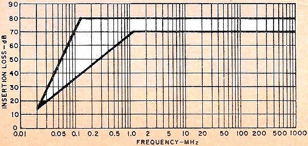
The minimum full-load insertion loss characteristics of subminiature EMI filters are measured in accordance with MILSTD-220 and usually fall within the band shown in diagram. Ideally, the loss characteristic is flat, however components resonating at specific frequencies cause some dips and peaks. Filter selection can be further complicated if the suppression of switching transients is required. Sometimes the addition of a shunt capacity to a circuit amplifies the signals it was intended to suppress. This characteristic is due to stored energy in the capacitor being discharged and creating large current loops which normally would not have existed. The assumption that a filter which provides 60-dB attenuation at 150 kHz in a 50-ohm system reduces interference in the system by that amount is, more often than not, erroneous. Most filter manufacturers, however, have personnel who are able to assist system designers and provide general filter-application guidelines. The major point, however, is that insertion loss cannot be assumed from a list of specs published in a catalogue. Proper consideration must be given to the system's characteristics. Once a filter which performs a desired function is specified, it is important that the same circuit configuration and approximate values be used in subsequent devices to assure system continuity. From the standpoint of cost and size, it is equally important that only necessary performance characteristics be specified. For example, if filtering is only required from 100 kHz through 1000 MHz, it is usually unnecessary to incorporate feedthrough capacitors. Less expensive capacitors and manufacturing processes will provide adequate performance. Also, unless lower frequency characteristics are actually needed, very high premiums in size, weight, and cost will result if attenuation within this range is also specified. In installations requiring low-frequency performance, it's desirable to use polarized electrolytic capacitors. This allows a much smaller package to have the same performance as a unit using conventional paper, ceramic, or film capacitors.
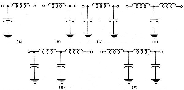
Here are electrical circuits of subminiature electromagnetic filters shown in photo above. The two L filters are found in parts 1JX1001-1002, respectively. Part 1JX1003 has a pi network (C) while T network (D) is found in part 1JX1004. Remaining double-L configurations (E, F) are found in parts 1JX1005-1006, respectively. The pi and L circuits handle 0.5 A; T and double-L, 0.4 A. Another factor in the cost vs. size battle between the product designer and product user relates to the specification of voltage, current, and temperature ratings. It is quite common for users who will need 2-ampere circuits to specify three or four amps as a safety margin. The cost and size for this luxury increase significantly, and are certainly out of proportion to the end result when the design capabilities of the manufacturer and his safety margins are considered. In order for a supplier of filters to minimize cost, weight, and size and yet provide the desired filter, the user should specify as nearly as possible his actual requirements in terms of insertion loss, current, voltage, and temperature ratings, and, if possible, the general circuit configuration in which the filter is intended to be used. As an added benefit, the user obtains the needed component quicker. In general, r.f. interference filters are conservatively rated with respect to voltage and current, Thus, they are widely used in military equipment where continuous operation within a specified ambient range is a must. |
|||||||||||||
 |
|||||||||||||
|
|||||||||||||


|
||||||||||||||||||||||||||||||||||||


