|
|||||||||||||
 |
|||||||||||||
Radio Mirrors for Communications
|
|||||||||||||
Passive repeater antennas have been used for a long time to overcome line-of-sight-limitations of many - if not most - of the radio communications universe. Properly designed and implemented passive repeaters can exhibit very high levels of efficiency, and in some cases can actually provide gain by focusing signals impinging on a large panel of multiple wavelength dimensions onto a smaller transmitter or receiver antenna. That is known as aperture gain. Optical telescopes are a good analogy where for the same level of magnification at a given wavelength, a larger aperture (refractive lens or reflector mirror) results in a brighter image at your retina or CCD detector. Interestingly, a passive repeater installation in Iran - a U.S. ally at the time - is mentioned in this 1969 Electronics World article. Iran fell into radical hands ten years later during the Iranian Revolution. Radio Mirrors for Communications By Ray D. Thrower /Field Services Manager, Microflect Co., Inc.
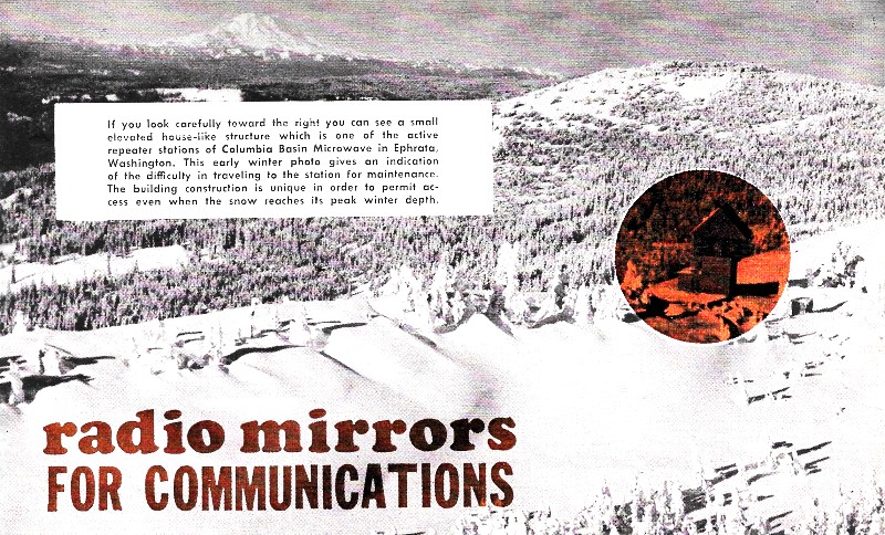
If you look carefully toward the right you can see a small elevated house-like structure which is one of the active repeater stations of Columbia Basin Microwave in Ephrata, Washington. This early winter photo gives an indication of the difficulty in traveling to the station for maintenance. The building construction is unique in order to permit access even when the snow reaches its peak winter depth. Huge passive reflectors, which actually provide gain of 100 to 130 dB for u.h.f. and microwave radio-relay stations, reduce installation and operating costs and keep noise to a minimum. Communications engineers are using large radio mirrors to redirect u.h.f. and microwave radio signals over and around mountains and tall buildings which would otherwise obstruct the radio beam. The use of the radio mirror, called a "passive repeater" in the communications industry, eliminates the need for large numbers of active radio-relay stations. The passive repeaters are replacing many active repeaters (with their transmitters, receivers, and parabolic transmitting and receiving dishes) and are reducing the cost of installing and operating high-density radio-relay networks. Microwave and u.h.f. radio beams behave quite a bit like light. They won't go through buildings or mountains or any other path "obstruction." For radio system design purposes, the solution to obstructed paths or for connecting points of communications used to be the installation of an active radio-relay repeater. In some cases this can be catastrophically expensive. With new advances in the techniques of reflector technology, it is now possible to design microwave communications systems without any active mountaintop repeaters whatsoever. Advantages of Passive Repeaters There are quite a number of economic and technical advantages cited by systems engineers and operators who have gone to the passive-repeater philosophy of communications system design. Active radio equipment requires continual maintenance. In the winter, in some locations, active-equipment failures can mean a cold, dangerous night for a maintenance man who must get to a mountaintop site to effect repairs. Special snow vehicles, an extra-cost item, are necessary to get to most mountaintops during the winter.
This passive repeater was installed high in the mountains of Glacier National Park, in Montana, for a large microwave radio telephone system. The passive repeater, once installed, requires little, if any, maintenance so that technicians working on such a system never have to go to isolated mountaintop sites in treacherous weather just to replace a blown fuse. This is an important factor to safety-conscious operations managers. Since the passive repeater requires no maintenance and no power, the cost of building an access road and running a power line to a repeater location is eliminated. The cost of access roads and power lines for an active repeater frequently exceeds the installed cost of a passive repeater. The passive repeater is also considerably less expensive than the active radio equipment. Some typical operating and maintenance costs for an active repeater are on the order of $1600 to $5000 per year depending on the complexity of the repeater station and its accessibility. Access road construction costs are from about $1000 per mile for simple graded roads across open country to $40,000 per mile, and more, in forested mountains. One microwave system operator reported paying $240,000 for one and one-half miles of access road. Passive Repeaters in Use
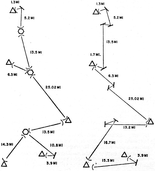
Fig. 1. Two methods of laying out a 600-voice channel, 6-GHz microwave telephone system being installed in western Oregon. System at the left uses active repeaters and seven sets of frequencies while system at the right uses passive repeaters and four sets of frequencies. Note that three active repeaters were eliminated at the right. Not only does this reduce the installation and maintenance costs, but a system noise reduction of 3 dB can be realized. Curved lines below are parabolic dishes of active repeaters; straight lines are passive reflectors. The passive repeater communications system can provide service equivalent to or better than that available from active repeater systems. Passive repeaters are being used to relay voice, video, and data communications in a multitude of systems around the world. The microwave backhaul systems from the new earth satellite stations in the Philippines, Indonesia, and Brazil use passive repeaters. A telephone company system in western U.S.A. has sixty-five passive repeaters. A 7-GHz system under construction in Iran will have 15 passive repeaters. The microwave backhaul link from the satellite earth station in Iran will also use a passive repeater. On the Island of Oahu, Hawaii, there are no less than twelve passive repeaters in four different systems. The passive repeater is being used in greater numbers than ever before in communications systems operated by oil pipelines, railroads, military and civil government agencies, and common carriers. All types of modulation are used in these systems. Active radio-relay repeaters contribute and amplify noise as well as the desired signal. Since the passive repeater provides passive "gain," rather than electronically amplified gain, it contributes no noise to the operating system. Active repeaters also produce intermodulation products in the radio-relay baseband. These intermodulation products are the result of the undesired mixing of different frequencies within the receiver or transmission lines and result in a gradual degradation of the information to be relayed. The radio mirror, being a passive device, contributes no intermodulation products to the signal. What About Gain? One thing that surprises most people is the fact that a passive repeater has gain. The question is always asked, "Gain, out of a flat surface? How can that be?" Gain has to be defined. It is generally accepted to mean an increase in level over a predetermined level. There are two types of gain available. One is by electronic amplification; the other is by aperture amplification. For electronic amplification, power must be applied or increased in order to get more gain. In aperture amplification, the aperture must be increased to get more gain. The passive repeater really gets its gain from the aperture it projects to the incoming and outgoing radio beams. In antenna-system work (a passive repeater actually forms an extended antenna system) gain is given in reference to an isotropic point source; that is, a source that radiates equally in all directions. Any change from an isotropic configuration will result in more energy being radiated in one direction than in another. Therefore, there will be gain in one direction, referred to the isotropic source. The passive repeater, with its large aperture, will result in considerable gain over an isotropic point source. For example, a 40-foot by 60-foot passive repeater, with a horizontal included angle of 90° for the radio beam will have a gain of 128.5 dB at 11 gigahertz. (A somewhat smaller reflector, shown on our cover, will provide a gain of about 110 dB in the 6-GHz band and 120-dB gain in the 11-GHz band. - Editor)
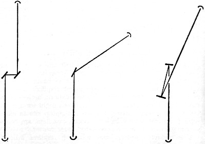
Fig. 2. Single reflectors are used for turn angles of up to 135°, as shown at the center. For greater angles, double reflectors, as shown at left and right, are used. Spacing between the two reflectors is not extremely critical. Depending on operating frequency and reflector size, the spacing may be from under 100 feet to over a mile or more without degrading the over-all system performance by more than a dB or so. Quite probably the difficulty many people have in understanding how the passive repeater, a flat surface, can have gain relates back to the common misconception about parabolic antennas. It is commonly believed that it is the focusing characteristics of the parabolic antenna that gives it its gain. Therefore, goes the faulty conclusion, how can the passive repeater have gain? The truth is, it isn't focusing that gives a parabola its gain; it is its larger projected aperture. The focusing is a convenient means of transition from a large aperture (the dish) to a small aperture (the feed device). And since it is projected aperture that provides gain, rather than focusing, the passive repeater with its larger aperture will provide high gain that can be calculated and measured reliably. A check of the method of determining antenna gain in any antenna engineering handbook will show that focusing does not enter into the basic gain calculation. Projected aperture is the effective "window" of energy seen by the antenna at the active terminal as it views the passive repeater. The passive repeater also sees the antenna as a "window" of energy. If the two are far enough away from one another, they will appear to each other as essentially point sources. Curing Fading Passive repeaters have been installed to cure fading of microwave signals due to unwanted ground reflections (multipath propagation) or ducting conditions. Installation of the passive repeater provides several advantages in a fading path. First, it offers angular discrimination to unwanted signals that might occur where the path goes over highly reflective terrain, such as flat land or water or even cloud or fog layers. Since the angle of reflection is equal to the angle of incidence, any unwanted signals being received from an angle other than the desired angle will be redirected off path and the magnitude of potential interference will be reduced. When there is ducting-type fading, the installation of a passive repeater can change the angle at which the microwave beam travels through the duct layer so that it is not so subject to being ducted off path. The sharper the angle at which the beam cuts through a duct layer, the less opportunity there is for the beam to be ducted away from the path. Installation of the passive repeater actually can change the path geometry to such a degree that the problems causing the fading may be done away with entirely. Engineers who design communications systems with passive repeaters have a different engineering philosophy than the engineers who put active repeaters on mountaintops. Quite a number of systems have been reconfigured to eliminate mountaintop active equipment, as shown in Fig. 1. Originally, this system, installed in western Oregon, was to have three active repeaters to connect the various communities. However, the engineers working on the system design decided to use a number of passive repeaters instead. By so doing they were able to do away with the need for three active repeaters in the 600-voice-channel common-carrier microwave system. The system has been partially completed and is operating according to design specifications.
Double passive repeaters are used when the turn angle for the microwave beam exceeds about 135 degrees. Each of these reflectors is 30 by 32 ft in size. One reflector receives energy from a 6-GHz telephone company radio terminal some 25 miles away and the other redirects as many as 600 simultaneous phone conversations to a receiving station about 6 1/2 miles away.
Fig. 3. The passive reflector need not reflect all the energy between the half-power points but merely the energy in the first Fresnel zone. The half-power points may be a mile or more apart after a distance of 30 miles while the radius of the first Fresnel zone at 30 miles with the energy being redirected for another 4 miles is only about 55 ft at 6 GHz. A reflector larger than this would reflect energy in the second Fresnel zone, which would be out-of-phase and cause destructive interference. By redirecting even a portion of the energy in the first Fresnel zone, it is possible to obtain practical gains of 100 to 130 dB. Plane reflectors are more efficient and less expensive than back-to-back parabolas. Another advantage derived is that frequency congestion in a given area is reduced by using a passive repeater. The all-active arrangement at the left in Fig. 1 would have required seven sets of frequencies where the passive-repeater system at the right will require only four sets of frequencies. This is a critical consideration where an area is approaching saturation of the frequency spectrum. Single passive repeaters are used where the angle to be turned, the horizontal included angle, is 135° or less. When larger angles are to be turned, the effective aperture of a single passive repeater would be small and inefficient so double passive repeaters are used to achieve high aperture efficiency (Fig. 2). Another area of difficulty in understanding the passive repeater is the matter of beam spreading. Many engineers and technicians believe the passive repeater must intercept all or most of the microwave beam between the half-power points (the -3 dB arc). After traversing a distance of 30 miles or so the half-power points of a 5-GHz microwave beam may be spread to almost one mile apart. The small antenna at an active repeater cannot even begin to intercept all the incident energy from a distant transmitter. In the case of the passive repeater, it is the Fresnel zone radius energy that is intercepted and redirected. For a 6.0-GHz signal traveling over a sixty-mile path, the radius of the full first Fresnel zone at midpath (30 miles) is only 112 feet. And since it is seldom necessary to intercept even all of this energy, the construction of practical-size passive repeaters is relatively easy (Fig. 3). It is necessary to keep the face of the passive repeater flat at microwave frequencies. This is mandatory since any distortions of the reflector face will degrade the signal. The face of the passive repeater must be flat to a tolerance of -1/8th wave length over the full face of the reflector. Notice that there is not a "+" tolerance factor. If there are any deviations from the flat reference point they must be concave rather than convex as a convexity would result in beam dispersal. The communications engineer will design his system on the basis of calculating each path rather than immediately ruling out passive repeaters on the basis of archaic "rules of thumb." No rule of thumb can possibly take in all the variables including: transmitter power, parabolic antenna size, path lengths, receiver threshold levels, and operating frequency. Another variable that must be considered is that of channel loading. How many voice or data channels will be carried on the radio? Or will there be video information? Recognizing the variables involved, the knowledgeable engineer will compute his paths to determine if a passive repeater will work or if, indeed, an active repeater is needed.
Radio mirrors are installed not only on snow-bound mountaintops but also in the tropics. This 30 by 40-ft repeater is installed on the island of Oahu and redirects a microwave signal capable of carrying 960 simultaneous voice conversations between Wahiawa and Honolulu, Oahu, Hawaii, a distance of over 23 miles. At a frequency of 6 GHz there cannot be any distortion greater than 0.164 inch over the full face of the radio mirror shown. The knowledgeable engineer or technician will also consider the economics of his active repeaters when they are necessary. Would it be less expensive to put the active repeater down by an existing access road (perhaps county or state maintained) and near existing power and then use a couple of passive repeaters on a nearby hilltop to provide the needed path clearance? Companies that specialize in the manufacture and design of passive repeaters frequently have both literature and seminar training sessions for interested groups at nominal fees. Usually, a letter request is all that is required to obtain technical data. References Chipp, R. D. & Cosgrove, T.: "Economic Analysis of Communications Systems". Seventh National Communications Symposium, Utica, N.Y. 1961. Jakes, W. C., Jr. & Robertson, S. D.: "Antenna Engineering Handbook". Edited by Henry Jasik. McGraw-Hill Book Company, Inc., First edition. Norton, M. L.: "Microwave System Engineering Using Large Passive Reflectors", IRE Transactions on Communications Systems, September, 1962. Thrower, Ray D.: "Passive Repeater Installations Can Reduce Microwave System Costs", Communications News, October, 1967. "Passive Repeater Engineering Manual Number 161", Microflect Co., Inc., Salem, Oregon. 1961. "Microwave Path Engineering Considerations - 6000-ENG", Lenkurt Electric Co., Inc., San Carlos, Calif. September, 1961. |
|||||||||||||
 |
|||||||||||||
|
|||||||||||||


|
||||||||||||||||||||||||||||||||||||


