|
October 1959 Electronics World
 Table of Contents
Wax nostalgic about and learn from the history of early electronics. See articles
from
Electronics World, published May 1959
- December 1971. All copyrights hereby acknowledged.
|
Germanium was "the"
semiconductor of choice in 1959 while advances were being made with silicon.
Most of the newer semiconductor devices were being fabricated with germanium as the
central transducer element. Temperature sensors, strain gauges, "sensistor" variable
resistance units, Hall effect sensors and gyrators and circulators, torsional (twist)
transducers, displacement sensors, and even neutron detectors were done in germanium.
Even though silicon is referenced as being applicable to all the devices, it was not
until the 1960s that silicon began to dominate semiconductor fabrication. This paper titled ,"From Germanium
to Silicon, A History of Change in the Technology of the Semiconductors," by
Philip Seidenberg,
does a nice job summarizing the transition period.
Novel Semiconductor Devices
Some interesting new and unusual semiconductor products along with a few of their
applications.
The usefulness of semiconductor materials, such as silicon and germanium, in the field
of transistors and diodes is well established. It might be reasoned that materials of
such wide usefulness in one area could also find applications in other areas and we find
this to be the case. Some of the properties of semiconductor materials, such as extreme
stability, temperature sensitivity, and sensitivity to magnetic fields, have been exploited
and several devices are now under active development in various laboratories.

Fig. 1 - Germanium resistance thermometer as it appears with the outer
case removed.

Fig. 2 - Pair of probe "Sensistors."
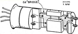
Fig. 3 - Cross-section drawing showing construction of germanium resistance
unit.
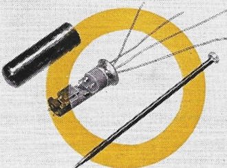
Fig. 4 - Germanium resistance thermometer compared in size with common
pin.
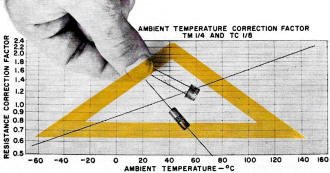
Fig. 5 - Ambient temperature correction factor curves for the "Sensistors"
shown. The factor from this curve multiplied by the resistance at a temperature of 25°C
will give the no-load resistance of the units at the desired ambient temperature.

Fig. 6 - A photograph of the Halltron HS-51 unit. Refer to text for
details.
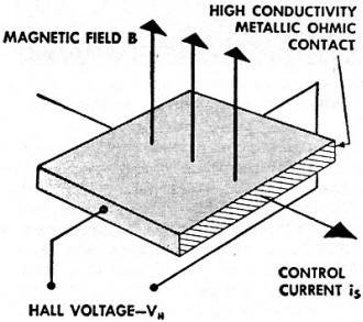
Fig. 7 - Semiconductor Hall Effect voltage generation is illustrated
here.
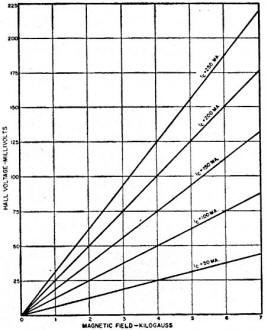
Fig. 8 - Hall voltages for typical Hall generator for various values
of control current and for various magnetic fields.
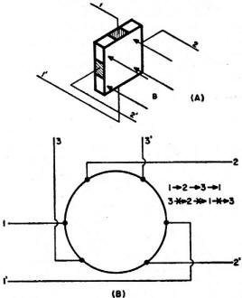
Fig. 9 - Basic diagram of (A) Hall Effect gyrator and (B) Hall Effect
circulator.
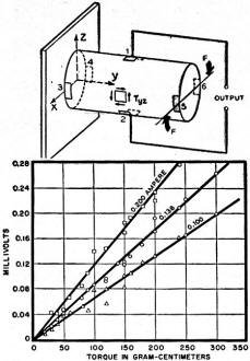
Fig. 10 - The torsional transducer. Graph shows calibrations at various
bias currents.
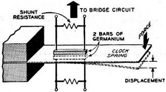
Fig. 11 - Displacement gauge constructed with germanium crystals.
Such gauges are up to two orders of magnitude more sensitive than common types that may
be used.
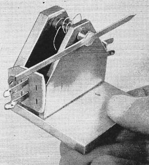
Fig. 12 - Shown above is a photograph of the torsional transducer
described in text.
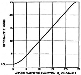
Fig. 13 - Resistance of typical MS-41 Magnetoresistor for various
magnetic fields.
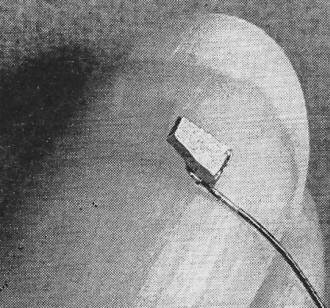
Fig. 14 - Neutron detector formed by a thin slice of germanium coated with uranium
layer.
Temperature-Sensitive Resistor
Single-crystal silicon has a very high positive temperature coefficient, that is,
its resistance increases very rapidly as its temperature rises. This characteristic has
been applied by Texas Instruments, Inc. in developing a device which has been trade named
the "Sensistor." This device has a positive temperature coefficient of resistance of
0.7% per degree C., which means that the resistance increases 0.7% for every degree the
temperature rises.
"Sensistors" are available with 1/4-watt and 1/8-watt ratings and a wide variety of
resistances. For the sake of comparison and uniformity, the resistance is usually given
at 25° C, which is normal room temperature. The actual resistance at any other temperature
can then be computed from a chart similar to Fig. 5, which gives the resistance at a
given temperature in terms of the value at 25°C multiplied by an appropriate factor.
As an example, suppose we have a nominal 100-ohm "Sensistor" and would like to know
its resistance at 50°C. Looking at the 50° point on the chart, we find that the multiplying
factor is about 1.18. Therefore, the resistance will be 100 x 1.18 or 118 ohms. Similarly,
we can compute the resistance value at any other temperature.
We can also compute the resistance by using the temperature coefficient and not referring
to Fig. 5 at all. In the example just given, the temperature increase (from 25°C
to 50°C) is 25°. Multiplying this by the temperature coefficient, 0.7% (0.007),
gives an increase of 0.18 ohm for every ohm of initial resistance. Since the initial
resistance was 100 ohms, the new resistance will be (100 x 0.18) or 18 ohms higher than
at room temperature.
It can be seen from these properties that the "Sensistor" can be employed as a sensitive
thermometer when used with an ohmmeter. A new scale for the ohmmeter can be calculated
without the laborious process of calibrating it. Care must be taken in applications of
this kind, however, to make certain that the measuring current flowing through the "Sensistor"
is not sufficient to alter its temperature due to this I2R loss.
For probing into very small spaces where temperature indications are desired, Texas
Instruments has developed a glass-encased probe "Sensistor." Its temperature-resistance
characteristics are very similar to the straight "Sensistor," but its mechanical construction
is quite different. It is made in the form of a cylinder about half an inch long and
less than one-tenth of an inch in diameter. See Fig. 2.
Many applications for the "Sensistor" are apparent, other than its possible use as
a thermometer. For example, it can be used to compensate for temperature changes in devices
having a negative temperature coefficient. It can also be employed in telemetering applications
where it is desired to transmit information on temperature back to a base location. Other
applications include amplifiers, power supplies, servos, and computers.
Low-Temperature Thermometer
Along somewhat similar lines, but operating in a completely different temperature
range, is the germanium low-resistance thermometer (Fig. 1) developed at Bell Telephone
Laboratories. Although not on the market as yet, this device is undergoing tests and
undoubtedly will be made by some interested company in the near future.
Extensive work is now being carried out in the field of cryogenics, that is, low-temperature
research. Temperatures involved may be in the neighborhood of the boiling point of helium,
4.2° Kelvin (4.2°C above absolute zero) and may range downward to within a fraction
of a degree of absolute zero or upwards to around 500K or so. Temperature-indicating
devices normally employed to cover this range are, in some cases, bulky and in other
cases require repeated recalibration, making them highly inconvenient to use.
The new thermometer, which is formed from a single crystal of n-type germanium, is
extremely stable and, once calibrated, holds its calibration very closely even though
repeatedly cycled from room temperature down close to absolute zero.
Fig. 3 shows the general construction of this device and the photograph of Fig. 4
indicates its size in comparison with a common pin. It is very small so as to be useful
in places where space is at a premium.
The active element is a bridge cut from a slice of germanium doped with arsenic to
make it n-type material. It also is a resistance thermometer, meaning that temperature
is indicated by measuring the resistance of the germanium slice. This is done by passing
a very tiny current through the slice and then measuring the voltage drop across it.
The actual resistance can then be computed from Ohm's Law:
R = E/I.
These thermometers have extremely high sensitivity, their resistance changing rapidly
with variations in temperature. For example, one unit tested had a resistance of 0.015
ohm at room temperature, 14 ohms at 10°K, and 216 ohms at 2°K. Both the temperature
coefficient and the actual resistance vary widely with minute changes in the amount of
doping, making it possible to construct thermometers having any of a wide range of characteristics.
It appears that the germanium resistance thermometer will have wide application -
from precise laboratory measurement of low-temperatures for cryogenic and calorimetric
work to sensing temperatures in outer space.
Strain Gauges
There is another property of semiconductor materials which is in the early stages
of exploitation by many laboratories but apparently no commercial devices are yet available.
This property is called piezoresistance-extreme sensitivity of the resistance of such
materials to tiny stresses and strains. Such a property makes these materials potentially
valuable as very sensitive strain gauges.
A strain gauge is normally made of wire. It is cemented to a beam, shaft, or other
device and will indicate very small bends or twists by a change of resistance. This resistance
change, in general, is quite small, requiring rather sensitive instruments if extremely
small motions are to be detected with any reliability.
By using a section from a single crystal of semiconductor material, sensitivities
of 10 or even 100 times as great as with conventional wire gauges appear possible. This
opens up a whole new field of application for germanium, silicon, and other semiconductor
materials.
These materials have other advantages over conventional gauges-they are stable over
a wide range of temperatures and respond accurately both to static strains and to varying
strains at frequencies up to the resonant frequency of the material employed.
Germanium appears to be useful up to 600°K., silicon to 1000°K., and the new
intermetallic semiconductor gallium arsenide may extend the temperature range up to around
1400°K.
Semiconductor strain gauges may be designed to measure either displacement, as shown
in Fig. 11, or torque, as indicated in Figs. 10 and 12. In the latter case, a cylinder
cut from germanium is cemented to the torque member and six leads attached. When provided
with appropriate biasing currents, a direct-reading sensitive torque meter results.
Pressure gauges made of semiconductor materials are extremely simple and reliable.
The materials are sensitive to pressure, that is, their resistance changes as the pressure
changes. Because of their stability and small size, such gauges can be immersed in many
different liquids and gases, and pressures measured by bringing two leads out of the
container.
Another desirable property is mechanical strength. In general, semiconductor materials
are relatively rugged and will withstand fair amounts of bending and twisting without
becoming permanently deformed.
The Hall Effect
From our basic electricity we remember that if a wire is carrying current while it
is in a magnetic field, there will be a force acting on the wire. This is the basic operating
principle of electric motors. If we were to explore the situation more fully, we would
find that the force actually acts on the free electrons which are carrying the current
in the wire and not on the wire itself. The net effect is the same, though, since the
electrons are confined in the wire. Any sideways force on the electrons is transferred
to the wire.
Because of this force, the electrons in the wire are pushed over to one side, leading
to an excess of electrons on that side and on the other side a deficiency. We might then
expect that a voltage would exist between the sides of the wire. This is exactly what
does happen, except that in good conductors the voltage is very small and hard to detect.
This is known as the "Hall Effect" and the voltage is called the "Hall Effect voltage."
The Hall Effect is a very useful tool in studying semiconductors, because in such
materials the effect is appreciable and the voltages produced can be measured readily.
In a semiconductor, the current may not consist entirely of a flow of electrons but may
also include the movement of "holes" or spaces where an electron is absent. As may be
expected, the magnitude of the Hall Effect depends on how easily these electrons and
"holes," usually called charge carriers, move around in the material. This property has
been termed "mobility." Greater mobility produces greater Hall Effect voltage.
Fig. 7 shows the results of the Hall Effect. Here we have a slice of semiconductor
material with current flowing through it. A magnetic field is perpendicular to the slice.
When these two conditions exist, a voltage will appear across the sides of the slice,
its magnitude proportional to the product of the magnetic field and the current. As a
typical example, if the current is 1/2 ampere and the field strength 10,000 gauss, the
voltage may be around 1/2 volt.
A commercial Hall Effect device is now on the market. It is manufactured by Ohio Semiconductors,
Inc. and is known as the "Halltron HS-51," which is shown in the photograph of Fig. 6.
The active part of this device is an intermetallic semiconductor known as indium antimonide,
a material which has a very high mobility - much higher, in fact, than silicon or germanium.
Many possible applications can be envisioned for the "Halltron HS-51" and similar
devices. The most obvious, perhaps, is the measurement of magnetic field strength. For
a constant current, the output voltage varies directly with the strength of the magnetic
field perpendicular to the slice of semiconductor material. Other possible applications
include a clip-on type ammeter, instantaneous power meter, d.c.-to-a.c. converter, and
perhaps in computers for analogue summation and multiplication.
Westinghouse has also announced the development of Hall generators using both indium
antimonide and indium arsenide. Voltages of 1/2 volt with a magnetic field strength of
5000 gauss and a control current of 1/2 ampere are obtainable with these devices. Fig.
8 shows the characteristics of a typical device. Output impedances can be adjusted from
0.01 to 20 ohms and their maximum frequency response ranges from 10 to 100 megacycles.
A study was made recently at Bell Telephone Laboratories of the many possible applications
of the Hall Effect. This study revealed that of the many possible uses two of the most
interesting are the gyrator and the circulator. These devices are sketched in Figs. 9A
and 9B.
The gyrator has probably received more attention than any other Hall Effect device.
By employing the gyrator in suitable circuitry, an isolator can be constructed in which
signals can be transmitted in one direction but not in the other. A germanium isolator
has been built with a forward loss of 14 db and a reverse loss of 75 db. Thus, the gyrator
could be used to isolate an antenna from a load, for example.
Fig. 9B shows what is known as a three-port circulator. In this device, signals can
pass from terminals 1-1' to 2-2', 2-2' to 3-3', and 3-3' to 1-1', but not in the other
direction, such as 2-2' to 1-1'. The circulator can be constructed from a slab of semiconductor
material with six equally-spaced edge contacts. Forward loss in a device of this kind
is about 17 db, and reverse loss in a typical n-type germanium slab may be as high as
64 db. A relatively high magnetic field is required with germanium, but a device of this
kind made of indium antimonide could operate satisfactorily with a relatively low field
of about 1000 gauss.
Because of the relatively high forward loss, Hall Effect devices of this kind must
normally employ a negative resistance amplifier for maximum usefulness. However, they
have the big advantage of theoretically being able to transmit d.c. signals as well as
a.c. signals at frequencies approaching the dielectric relaxation frequency of the semiconductor
material.
Other Hall Effect devices which have been explored, either experimentally or theoretically,
include a negative resistance amplifier, mechanical transducer, electrical compass, modulator,
and demodulator. These devices do not involve p-n junctions and so the surfaces do not
need elaborate protection.
Magnetoresistance
As mentioned before, when a slice of current-carrying semiconductor material is placed
in a magnetic field, the charge carriers are pushed over to the sides of the slice in
a direction perpendicular to the current flow. This has the effect of increasing the
resistance of the slice. Here, then, we have a device whose resistance can be altered
by changing the strength of the magnetic field in which it is placed.
This effect is known as "magnetoresistance."
Ohio Semiconductors, Inc. has developed a device utilizing this effect and has trade named
it the "Magnetoresistor." The type MS-41 utilizes a thin slice of indium antimonide,
again because of the high mobility of the charge carriers in this material. A resistance
change of as much as 1 to 10 can be obtained with a change in field strength from zero
to 10,000 gauss. The change in resistance is proportional to the square of the magnetic
field up to about 7000 gauss and is then directly proportional to field strength to over
20,000 gauss. A typical characteristic curve is shown in Fig. 13.
This device has many possible applications, including a contactless potentiometer,
modulator chopper, amplifier, and regulator. The MS-41 has a zero-field resistance of
one ohm, but units having values ranging from 0.01 to 50 ohms are being developed.
Neutron Detection
One of the most unusual applications of semiconductor materials was recently announced
by Westinghouse Electric Corp. Scientists at Westinghouse have developed a neutron detector
made of a tiny slice of germanium or silicon no larger than the head of a pin. The slice
is treated to form a p-n junction and a very thin layer of uranium is spread on the top
surface.
Slow-speed neutrons strike this uranium layer and cause U-235 atoms to split apart
just as they do in a nuclear reactor. The high energy products of this fission produce
an electrical pulse at the p-n junction, and so can be counted. Fast neutrons do not
produce fission and so are not counted, nor are gamma rays.
If desired, this neutron detector can be converted to count fast neutrons by replacing
the uranium layer with a material rich in hydrogen, such as paraffin.
Accurate mapping of both slow- and high-speed neutrons is a necessity in a nuclear
reactor. Because of its very small size, this detector can plot neutron flux variations
down to dimensional changes as small as one twenty-fifth of an inch. Thus, this neutron
detector can be a highly useful device wherever accurate neutron mapping is necessary.
The size of the detector is indicated in Fig. 14, where it is shown resting on a man's
thumbnail.
Conclusion
We have discussed here a few of the many possible applications of semiconductor materials,
based on phenomena which have been explored intensively. Which of these will find wide
usage is very hard to say at this time, but it is obvious that they are all of great
interest. They are all products of the intensive research into the properties of semiconductor
materials which was sparked by the invention of the transistor at Bell Telephone Laboratories
in 1948.
Posted July 4, 2018
|


