|
April 1967 Electronics World
 Table
of Contents
Wax nostalgic about and learn from the history of early electronics. See articles
from
Electronics World, published May 1959
- December 1971. All copyrights hereby acknowledged.
|
As reported in this 1967
Electronics World magazine piece, lasers were still the things of
science fiction to most people. Real-world applications seemed to be far off in
the future, but in fact, work was underway setting the stage for today's
blazingly fast communications systems. The author here references attaining 5 THz optical
transmission speeds through fiber and through the air. At the time, a laboratory
filled with bulky prototypes chassis and optical tables were required to get those
results. I can remember reading articles in the 1970s when laser power output
was measured in "Gillette
power," referring to the beam's ability to burn through a number of razor
blades (a big deal at the time). In 2020, devices that greatly surpass 5 THz are available in consumer
quality IC packages for a couple dollars. Such is the way or progress.
Laser Modulators
Although still in the R&D stage, three new light modulators allow a laser
to be used as a broadband light transmitter. Bandwidths up to 7000 MHz have been
reported for one unit.
GHT modulators developed at Bell Telephone Labs., now make it possible to modulate
broadband communications signals onto laser beams, using low-level modulators requiring
less than one watt of power.
The three devices to be discussed are highly efficient modulators of both pulsed
and continuous laser light. The first two work on the well-known principle of polarization
in which a light beam is passed through two polarizers. When the two polarization
planes are rotated so that they are 90° from each other, no light will pass through.
When they are aligned parallel to each other, the light will pass through almost
undiminished. By adjusting the polarization planes' relative angle between parallel
and 90°, it becomes possible to intensity-modulate the light beam.

Fig. 1 - The lithium tantalate modulator is capable of 896
megabits per second, and may soon attain 5000 megabits.
Lithium Tantalate
This electro-optic digital transmission modulator system (Fig. 1) has been
used in an experimental system for high-speed transmission of pulse-code modulation
(PCM) signals. In PCM systems, information to be transmitted (TV, voice, or data)
is translated into a coded sequence of electrical pulses (bits), with each bit representing
a discrete signal level.
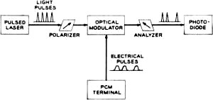
As shown in Fig. 1, pulses of light from the laser are first passed through
an initial polarizer that causes the light beam to assume a particular polarization.
After passing through the polarizer the light then passes through the moulator,
a thin rod of lithium tantalate crystal (measuring 0.4 x 0.01 x 0.01 inch). The
light then encounters the analyzer filter having s a plane of polarization 90° different
than the polarizer so that the laser light will not pass through the analyzer and
be transmitted to the photo-diode detector.
The lithium-tantalate crystal modulates (in this case modulation consists of
polarization changes) the incoming light and acts as a high-speed gate. Two electrodes
are plated on opposite rectangular faces of the crystal and when the PCM terminal
sends an electrical pulse (representing a "1") to these electrodes, it causes the
plane of polarization of the light passing through the crystal to shift 90 degrees.
This change allows the light to pass through the analyzer and be detected by
the photodiode. If no electrical pulse (representing a "0") is sent from the PCM
terminal, the light passing through the crystal is blocked at the analyzer, hence
it does not get to the photo-diode. The electro-optical modulator uses this coded
sequence of high-speed electrical pulses to modulate (gate) an equally fast train
of light pulses from the laser.
The speed of operation of this system is about 224 million bits per second. After
some redesign of the modulator, it is expected that operational speed will reach
896 million bits per second. This latter rate is equivalent to a bandwidth of about
1600 MHz. It is hoped that future systems, using a solid-state laser having extremely
narrow pulse widths, may reach speeds of 5000 million bits per second.

Fig. 2 - The YIG modulator can transmit 33 TV programs.
YIG Modulator
This modulator consists of a rod-shaped crystal of gallium-doped yttrium iron
garnet (YIG) with a small coil wound around it, and the crystal submerged within
a magnetic field. It operates on the principle discovered by Michael Faraday in
1845 that the plane of polarization of a light beam in a magnetic medium rotates
along the magnetic lines of force. The application of current to the coil surrounding
the doped YIG rod creates a second magnetic field in the crystal, at right angles
to the first. If the current flowing through this coil is the result of a varying
signal, the plane of polarization of the light beam passing through the modulator
will also vary in accordance with the modulation.
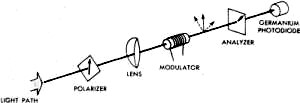
Operation is shown in Fig 2. The light output from the laser is first sent through
an initial polarizer that causes the light beam to assume a particular polarization.
A lens focuses the light beam through the modulator and onto the analyzer filter.
The analyzer has a plane of polarization 45° away from the polarizer.
The modulation current is allowed to flow through the YIG coil, the magnetic
field within the YIG varies, thus the plane of polarization of the light leaving
the YIG varies, and is allowed to pass through the analyzer at various light levels
ranging from no light to maximum light.
This modulator has exhibited bandwidths of 200 MHz (sufficient to transmit about
50,000 telephone calls or 33 TV programs). Another version of the modulator has
reached a 400-MHz bandwidth; however, maximum potential bandwidth has not yet been
determined.

Fig. 3 - The gallium phosphide modulator reaches 7000 MHz.
Gallium Phosphide
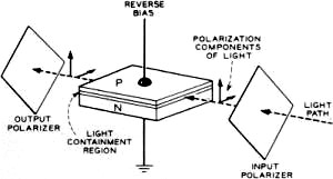
This modulator, shown in Fig. 3, consists of a semiconductor diode p-n interface,
together with mounting and input/output lenses (not shown). The incoming laser light
is divided into two equal components at the input polarizer, then focused on the
p-n interface. The light passes through the diode and is confined within the p-n
interface because of the discontinuities in the index of refraction along both upper
and lower surfaces.
When reverse bias is applied to the diode, the gallium phosphide in the junction
region changes from an optically isotropic (having the same properties in all directions)
medium to a medium having different optical properties in different optical properties
in different directions. This anisotropy causes the two polarization components
of the incoming light beam to travel at different velocities through the p-n interface.
This change in relative velocities, in essence, phase-modulates the passing light
beam in accordance with the reverse bias (modulating signal) across the junction.
Intensity modulation results from passing the phase-modulated components through
the output polarizer.
This diode has successfully modulated a laser beam up to 7000 MHz, with optical
losses of less than 3 dB.
These approaches show that laser transmission systems to replace microwave relays
may not be too far off.
Posted April 14, 2020
(updated from original post on 4/28/2012)
|


