|
|||||||||||||
 |
|||||||||||||
Ionospheric-Propagation Predictions
|
|||||||||||||
Much has been learned and published about the various layers of the ionosphere since its first being measured with sounding rockets in the 1950s. Both professional and amateur communications operators are very interested in its properties. Long term (seasonal) and short term (daily) patterns have been discerned that help make some of the ionosphere's effect on the propagation of electromagnetic (radio) signals somewhat predictable, but there are still many unpredictable events that hamper - and often enhance - communications. Sun spots and coronal mass ejections, volcanic eruptions, hurricanes, and other natural events cause sporadic changes in the ionosphere. Real-time atmospheric propagation conditions are monitored and reported on many websites worldwide (see dr2w.de, dx.qsl.net, dxmaps.com, hamsql.com, sws.bom.gov.au, hflink.com, iono.jpl.nasa.gov) The quality of a long-distance communications system depends on the ability of the ionosphere to bend and reflect radio waves back to earth.By H. Charles Wood
Fig. 1 - Groups of well-formed sunspots (arrows) photographed in February 1956 near the maximum of an 11-year cycle. Ultraviolet radiation during height of solar cycle is sufficient to produce highly ionized F2 layer capable of supporting radio signals of frequencies up to 50-55 MHz. Some radio waves penetrate the ionosphere and fly outward to the stars; others are stopped, bent, and reflected to touch the earth miles away from their origin. Propagation - the movement of electromagnetic (radio) waves through the air, or "ether" as it used to be called - is the means by which wireless communications systems communicate. The distance over which these waves travel is a function of frequency; angle of radiation; and atmospheric noise such as sunspots, aurora borealis, and other solar activity. This article discusses the various phenomena which must be considered when predicting propagation distances. Ground Wave and Sky Wave Engineers agree that radio waves are electromagnetic waves consisting of traveling electrostatic and electromagnetic fields of energy whose lines of force are at right angles to each other in a plane perpendicular to its path. Except for frequency, the electromagnetic field has the same characteristics as light waves - both have a speed of 300-million meters per second, and both are capable of being refracted or reflected. Two types of electromagnetic waves are emitted by a transmitting antenna, one travels along the ground and is called the ground wave. The other, referred to as the sky wave, travels through the atmosphere and has little contact with the earth along most of its path. At low frequencies (below 500 kHz), the ground wave is the most important, frequently traveling a thousand miles or more. In the broadcast band, ground waves are received 200 miles or more away over land and perhaps twice that distance over sea water. At higher frequencies, however, the range drops off rapidly. Above 4 MHz, the ground wave is only useful for very short distance communications. The sky wave leaves the transmitting antenna at various angles of elevation to the earth's surface, ranging from 1 or 2 degrees to 90 degrees, and would travel out into empty space were it not that, under certain conditions, it can be reflected or refracted high in the atmosphere to return to the earth at distances varying from zero to about 2500 miles (4000 kilometers) from the transmitter. By a series of alternate reflections by the upper atmosphere and the earth's surface, electromagnetic waves can be transmitted or propagated around the world. Ionosphere
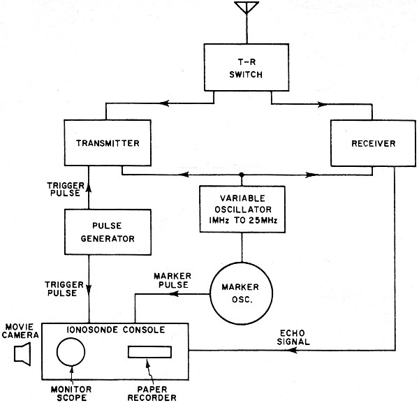
Fig. 2 - Block diagram of a typical ionosonde. This radar-type device explores the ionosphere and records the MUF for a specific time of day. There are 150 observatories around the world. The medium which causes the bending or reflection of the sky wave is called the "ionosphere", a region in the upper atmosphere where free ions and electrons exist in sufficient quantity to cause a change in the reflection index. Ultraviolet radiation by the sun is considered to be responsible for producing most of the ions. In the ionosphere, ionization does not change at a uniform rate, that is, proportionate to height, rather the ions form in layers with each layer consisting of a highly concentrated central region, tapering off in intensity above and below this area. Three major layers of ionization exist in the upper reaches of the atmosphere: the "D" region, "E" region, and "F" region, with the F layer being further subdivided into F1 and F2. The D-region, lowest of the ionospheric layers, ranges in height from 30 to 50 miles above the earth. At this altitude the atmosphere is still relatively dense and atoms broken into ions by solar radiation quickly recombine. Here the amount of ionization is directly dependent upon the amount of sunlight. Therefore, it is maximum at noon and almost zero at dusk. In the D-layer, most electromagnetic wave energy (sky waves under 5 MHz) is expended in the form of heat. Thus, the D-layer acts as an absorber with little effect on bending radio waves back to earth. The E-layer, the second significant ionized layer in the atmosphere, has a mean height of about 6.5 miles and because it, too, is in an area of comparatively high atmospheric density, ionization varies with the elevation of the sun, much the same as the D-layer, although not to as great an extent. And, also for reasons mentioned previously, a radio wave below 5-7 MHz passing through the E-layer loses a large portion of its power in the form of heat. The F-layer, the third and most important ionized area for long-distance short-wave communications purposes, is approximately 150 to 250 miles above the earth. At this altitude, the atmosphere is so thin that electrons and ions are slow in recombining. Ionization reaches a maximum shortly after noon and decreases very slowly to a minimum shortly before dawn. At sunrise, intensity increases rapidly to a maximum within an hour or two. During daylight hours, the F-layer sometimes splits into two distinct areas, called the F1 and F2-layers. The F1-layer is of little importance to radio communications except that it acts as an absorber much like the D- and E-layers and disappears shortly after sunset. The F2 region of the ionosphere is normally the most important parameter in estimating the performance of a high-frequency transmission but, unfortunately, it is also the most unpredictable of the three ionospheric layers. The Critical Angle The amount by which a radio wave is bent in the F2 region is dependent upon two factors: the density of the ionized layer, and the frequency of the wavelength. The greater the ionization, the more it bends at a specific frequency; or for a specific degree of ionization intensity, the refraction will be greater as the frequency is lowered. It thus becomes apparent that if the ionization is intense enough and the frequency is low enough, a radio wave entering the F2-layer at a 90-degree angle will be reflected back to earth; conversely, if the frequency is raised or the amount of ionization is decreased, a point will be reached where the refraction will not be sufficient to return the radio wave. Fig. 3 shows a specific radio wave whose frequency is of such a value as to penetrate the ionosphere at a 90-degree angle but is reflected back to earth when the angle is decreased. The angle at which the radio wave begins to bend back toward earth is called the critical angle. Fig. 3 also shows low-angled waves being bent back to earth in a single-hop propagation. As mentioned earlier, multi-hop transmissions are accomplished by alternate reflections of the electromagnetic wave between the earth and the F2-layer. Because long-distance high-frequency radio communications depends upon the ability of the ionosphere to return the radio signals back to earth, it is apparent that predictions of ionization intensities in the various regions of the F2 and other layers are essential to the calculation of sky-wave circuit (the communications path over which intelligence is transmitted) performance. Predictions of the F2 characteristics are computed about three months in advance by the Environmental Science Service Administration and published in a booklet called "Ionosphere Propagation Predictions." These predictions, as well as the accompanying isograms which show the maximum usable transmitter frequency for a specific hour of a specific month, are essential tools for the communications engineer. A discussion of the methodology used by ESSA in the compilation of the charts appears later in this article. The mechanics involved in using the charts are beyond the scope of this article; however, they are described in ESSA Handbook #90. The Optimum Frequency
Fig. 3 - Typical daytime ionosphere layer diagram showing high-angle radiation penetrating the F2-layer, but reflected back toward earth as the wave-angle is reduced. All multi-hop transmissions are at wave-angles below the critical angle. The complexity of the propagation phenomenon, the diversity of radio programming services, and the fluctuations in traffic density within the high-frequency bands preclude any clear and simple criteria for the selection of optimum frequencies. And because these are elusive factors, a high-frequency communications engineer's job is not an easy one. Since the density of the F2-layer and its height above the surface of the earth vary with the time of day and the season of the year, and because of the 11-year sunspot cycle (a factor we shall discuss later), it is common practice for communications engineers to select a new set of operating frequencies and time schedules every three months. In general (within the high-frequency spectrum), radio noise tends to decrease as frequency increases; also, propagation losses become less severe as frequency increases. Therefore, the higher the operating frequency the better the signal-to-noise ratio. However, the frequency can be increased to a point where the critical frequency is exceeded, or where the ionosphere reflection becomes improbable. This point is called the Maximum Usable Frequency (MUF). Through the use of the prediction charts and a working knowledge of the geographic variation in the electron density of the F2-layer, it is possible to predict this upper limit. It would therefore seem to the engineer's advantage to simply operate very close to the MUF. Unfortunately, the high-frequency circuit calculation is not that simple. Because the F2-layer density changes constantly, it would be necessary to continuously change the operating frequency throughout a 24-hour day - a laborious task to say the least. If enough is known about the ionosphere to determine the critical angle, etc., at specific frequencies 90 percent of the time, these frequencies are considered adequate as estimates of upper limits for system planning. Selected operating frequencies are approximately 10 percent below the MUF. This minimizes circuit interruptions from irregularities in ionospheric conditions and reduces to a minimum the number of frequency changes required to maintain acceptable continuity throughout the transmission period. This operating frequency is called the Optimum Traffic Freq. (OTF). Because energy absorption in the ionosphere's D- and E-layers increases as frequency decreases (assuming that the transmitter's output power remains constant), the power available at the receiver's input decreases. The atmospheric noise level also increases with a decrease in frequency. These phenomena combine to lower the signal-to-noise ratio and reduce circuit reliability. When the required signal-to-noise ratio (the minimum acceptable level for communications) equals the available signal-to-noise ratio, the circuit may be expected to have acceptable quality on half the days within the month. In other words, the probability of satisfactory performance on any given day will be 0.5. The probability of satisfactory signal-to-noise ratio at any given hour is defined as circuit reliability. As the available signal-to-noise ratio exceeds the required signal-to-noise ratio, circuit reliability increases. Since the available signal-to-noise ratio decreases as the transmitter frequency is decreased, it becomes apparent that a point can be reached where a further reduction in frequency will result in unacceptable circuit reliability. This point is defined as Lowest Useful Frequency (LUF). The LUF depends on transmitter power, the factors that determine the path-loss (frequency, season, geographic location), and noise level. Of course, one of the principal factors is D- and E-level absorption and, since their intensity is maximum at noon, LUF is highest at noon. When calculating an operating frequency, the engineer must select one that is above the LUF but not greater than the OTF. Selection of Frequency Complement Absolute continuity of any high-frequency radio service is impossible to achieve even if an unlimited choice of operating frequencies is available. For a 24-hour day, frequency complements are based on the concept of Maximum Feasible Continuity or that a theoretical increase in circuit continuity will be negligible if additional frequencies are used, but a significant decrease in continuity is possible if fewer frequencies are used. The required frequency complement depends upon the type of circuit used. Communications engineers classify all circuits in two groups: circuits requiring Maximum Feasible Continuity and circuits requiring Moderate Continuity. Circuits requiring maximum continuity are heavily loaded telegraph and telephone circuits which maintain high traffic at all times. Telegraph circuits in this category are usually operated by high-speed machines which transmit 100 or more words per minute, while telephone circuits generally employ several multiplex channels of a single-sideband system with multi-line terminations at each end. Such circuits usually have large directional antennas and employ diversity reception and high-power transmitters. The standard frequency complement for these circuits assures at least one frequency between OTF and LUF at all times plus two additional frequencies to permit flexible operation in the event of atmospheric disturbance. When choosing frequencies for this service, the communications engineer selects one high frequency, one low frequency, and one middle frequency. The high frequency is strictly a daytime frequency (computed to be well below the OTF for at least four hours every day during the period the circuit is operated). The low frequency of the three-frequency complement is exclusively a night channel, and is chosen as the highest frequency for which less than two hours of skip is indicated on the lowest of the OTF curves for the required operating period. The middle frequency selection is made to maximize the number of hours during which at least one frequency is between LUF and OFT for the required circuit operation. Circuits requiring only moderate continuity are usually those that provide communications where the needs are sufficiently critical to warrant extension of telephone, cable, or v.h.f. facilities. Many such circuits are used to provide occasional service to remote areas or are operated in situations where occasional delays or traffic slow-downs can be tolerated. The standard frequency complement for these circuits is usually one day frequency and one night frequency. Therefore, the logical selection for the daytime frequency must be one that will be above the mid-day LUF but far enough below the OTF to give skip-free service to the intended areas. The night-time frequency is chosen as the highest frequency for which less than four hours of skip is indicated on the lowest OTF curve for the operation period. Solar Activity As mentioned earlier, solar bombardment of the earth's upper atmosphere by ultraviolet rays is the major influence in the production of ionized layers. Because the earth is constantly bathed by these rays, the F2 layer is always present; however its density and height above the earth changes constantly. Although a completely satisfactory measure of solar activity is not available, the average number of sunspots over a 12-month period (as observed at Zurich, Switzerland) has formed the basis for much of the radio propagation analysis, and is presently being used as an index of the solar activity. Other celestial occurrences are under study at this time in an effort to improve predictions. A linear relationship between the F2-layer and the sunspot number was first established in the early 1930's. Observations made during the succeeding 11-year solar cycle continued to correlate well with the sunspot number. This led to the conclusion that, from a practical point of view, it seemed advisable to use this phenomenon as a basic reference point. Generally speaking, as the sunspot number increases during the given 11-year solar cycle, the F2-layer increases in density and altitude, permitting the higher frequencies to "open up" to various parts of the world. Fig. 1 shows a group of well-formed sunspots observed in 1956. Three other sunspot variations must be taken into account when predicting solar activity: (1) solar rotation (which lasts about 27 days; this causes the longer-lived sunspots to reappear several times on the earth-side of the sun's surface); (2) seasonal changes brought about by the difference in solar bombardment reaching the two hemispheres during the winter and summer months; (3) detectable waxing and waning of sunspot numbers over long periods of time (one hundred years or more). Occasionally, during times of maximum 11-year cycles, tremendous bursts of solar energy, called "flares", eject highly charged electrified particles millions of miles into space around the sun. Energy bursts such as these often cause the F2 layer to temporarily disappear, bringing about a complete radio circuit breakdown above about 4 MHz. Ionospheric Soundings It is apparent that for purposes of radio communications, it is necessary to have as much information as possible about ionospheric characteristics. Therefore, sounding stations have been installed in more than 150 locations around the world to provide a steady flow of solar data to a central location where it is analyzed, computed, and relayed to users. Height and density of the F2 layers are obtained at the sounding stations by the use of an ionosonde, a pulse radar device in which the exploring frequency can be varied over a wide range of frequencies from about 1 MHz to 25 MHz. The ionosonde is equipped with an antenna system to direct radio energy at a 90-degree angle and is designed to measure the elapsed time for a pulse to travel to the F2 layer and return. As the frequency of the ionosonde is increased, the point at which the radio signal is no longer returned is recorded. This is the Critical Frequency. Fig. 2 is a diagram of a typical ionosonde.
Posted June 6, 2023 |
|||||||||||||
 |
|||||||||||||
|
|||||||||||||


|
||||||||||||||||||||||||||||||||||||


