|
|||||||||||||
 |
|||||||||||||
RF Induction Heating
|
|||||||||||||
If you are interested in the ingenious machines and methods manufacturing engineers dream up for quickly and reliably producing parts and assemblies in large volumes, then you will definitely appreciate this article on RF induction heating. This process of course only works with metallic objects, unlike microwave type heating schemes that work with liquids. Induction heating requires the generated electric, magnetic, or RF field to invoke electrical currents within the metals to increase its temperature. Ohm's law applies here. Have you ever used a torch to heat a metal bolt, wire, car fender, etc., and noticed how it usually discolors the surface and might even produce a crusty oxide layer? An extreme temperature rise as is required for soldering, brazing, or welding can, in addition to discoloring, alter the temper of the metal. I have used a butane torch many times to heat music wire for bending model airplane landing gear, braces, and other items and have to be careful not to destroy the temper characteristic that provides the correct amount of springiness. Improper temper can make the wire mushy or even brittle rather than flexible. Induction heating eliminates the problem in most cases because the temperature rise is very localized. Appended to the end of this article was a special feature titled, "Melting Silicon for Semiconductors." Here is a superb video demonstrating and explaining the action of induction heating. Lots of videos are available showing production use of induction heating systems. Induction Heating
Induction Heating Corporation The story of how electronics is used to produce controlled heating in many branches of industry. The operator holding a gold ring into a fixture for a second then wiping it quickly is actually brazing the ring. Her hands do not get burned, there is no flame, yet each ring she brazes comes out perfect, without discoloration and without having to be cooled. The secret-electronics does the heating! In the manufacture of transistors and diodes, silicon is grown into large single crystals at a heat of 1400° centigrade. This is done in a vacuum or in a controlled atmosphere and the temperature must be maintained within ±25°. Again electronic heating does the job. In many other applications such as hardening, tempering, soldering, etc., the heat is generated without fire, without sparks, without heating up the air or the surrounding tools. Only the point where the heat is needed gets hot, quickly and at a controlled temperature.
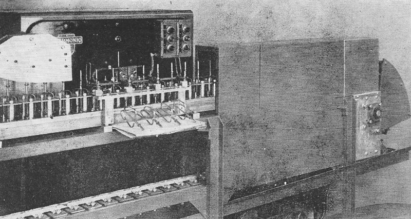
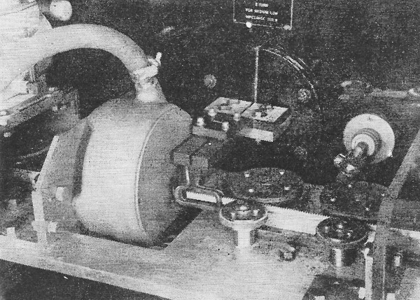
Fig. 1 - A conveyor carries beaters for home mixing machines through this induction heating unit which brazes the beater blades to the main stems automatically. As many of our readers know, induction heating is employed widely in research and production in the electronics industry. This is especially true in the component manufacturing field where tubes, transistors, diodes, capacitors, and transformers are often brazed, welded, or soldered into their containers. In addition to the electronics industry, induction heating has found wide application in all branches of metal working and allied industries. It would be impossible to describe, or even mention, all of the possible applications of induction heating. Mentioned below are a few of the more common applications where electronic heating takes the place of the torch or the smithy. An example of one application of v.h.f. energy is the apparatus shown in Fig. 2 which is used for zone-refining of ultra-pure silicon, ferrite materials, etc. This machine operates at 120 mc. and at this frequency it is possible to keep a zone-refining process going in yttrium iron garnet, a material used in the recently publicized solid-state microwave amplifiers. The double glass bells surrounding the work piece serve as vacuum chambers and safety shields respectively. At the control panel (shown at right) the various critical parameters are adjusted while the main r.f. generator is located behind the glass bells. One application of induction heating that may be of particular interest to our readers is soldering. Whether it is the sealing of a transformer in its shield can, joining a feedthrough terminal to a glass bead, or the assembly of microwave cavities, induction heating allows us to solder quickly and with such concentrated heat that other delicate parts in the assembly do not get warm. Here are some other uses.
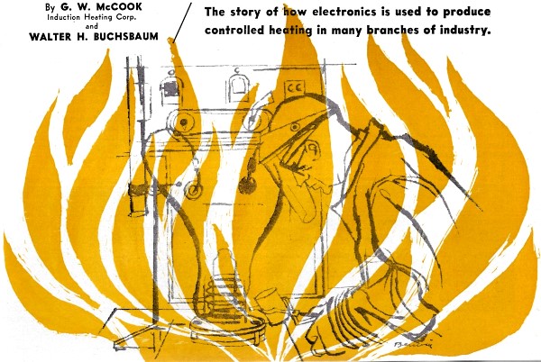
Fig. 2 - The v.h.f. energy is used here for zone-refining silicon. Double glass bells are used as vacuum chambers and shields. As an example of a typical automatic installation Fig. 1 shows an induction heating machine of the vacuum-tube type, coupled with an automatic conveyor and handling system for the mass production of beaters used in home mixing machines. Here the brazing of the beater blades to the main stem is done automatically. The total heating time is only 3 seconds, not long enough to discolor the stem or in any way damage the temper of the blade. Other products whose manufacture involves brazing by induction heating include ice skates, spark plugs, curtain rings, and many other consumer items as well as all types of industrial equipment. Low-frequency induction heating is usually employed to heat the entire work piece and not just a part of the surface. Low-frequency power is delivered to the work coil by one of three methods. In a few cases the work coil can be designed to connect directly to the 60-cycle power line, but more often a transformer is used to match the work coil impedance to the line. Where higher powers are used, a rotating motor-generator set delivers the heating power, usually at a frequency higher than the 60-cycle line. Typical are 960, 3000, and 10,000 cps. One novel application of low-frequency induction heating is as a metal melting furnace. Operating at 960, 3000, and 9600 cycles, Allis-Chalmers makes such furnaces with output ratings up to 1250 kw. Because the application of heat is quite fast and only the metal to be melted is heated, there is less oxidation, forming of scale, and other wasteful side effects which are inevitable with conventional furnaces. An unusual device is the "Frequency Transformer," made by Induction Heating Corp., which generates 180-cycle power from a 3-phase, 60-cycle line without any rotating machinery. A transformer-like device, capacitors and resistors form an RLC network which efficiently generates the third harmonic of the power-line frequency. This equipment, in addition to metal melting, is used for heating relatively large metal pieces such as bearings or housings for shrink fitting. In the metal working industries induction heating finds wide application in the hardening and tempering of bearing portions of moving machinery. The gear tooth-hardening process in Fig. 3 is typical. Here the rack gear teeth of a business machine are hardened at the rate of one-inch-per-second. At the right, out of the picture, is a magazine containing a sizable stack of racks, which are fed into the rollers one after the other. The rack passes through the specially shaped work coil for heating. While still hot, the rack is fed into a circular quenching chamber at the left and finally the rack emerges hardened along the teeth and back edge leaving a tough area between. Other typical hardening applications include the bearing area of turbine shafts, cutting edge of blades, tool bits, drills, and practically every piece of metal which is subject to wear. Hot forming processes such as forging, bending, etc. can all be done more efficiently by using induction heating. In bending, for example, only the area of the bend itself need be heated and since induction heating does this so quickly, the rest of the work piece will remain rigid and retain its shape. Fig. 4 shows a moving coil fixture in which an aluminum door handle is heated to 900° F and bent at right angles in 3 seconds, the entire operation being completely automatic, accurately controlled, and without forming scales, discoloring, or distorting.
Fig. 3 - Automatic hardening of typewriter ratchet gear teeth.
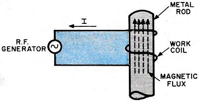
Fig. 4 - Moving coil fixtures for heating, bending door handles. Shrink fitting of bearings is another typical use of induction heating equipment. A work coil which fits inside the hole heats up the metal sufficiently to expand the hole diameter and then the shaft or other part is quickly inserted in the hole. As the metal cools it grips the insert firmly and produces a reliable, tight fit. In addition to the few examples outlined here, there are a host of special purpose applications where induction heating is often the only method which permits the efficient production of a particular metal part. Whenever metal must be heated, induction heating offers a rapid, efficient, and easily controllable source of heat. The basic reason for this lies in the principle of induction heating-the heat is generated electronically, directly in the work piece itself. How It Works The device that generates the power for the induction heating process is very similar to a radio transmitter. It takes low-frequency power from the power line and converts it into a high-frequency signal. In an ordinary radio transmitter the signal is sent out over the antenna and radiates through the air. In addition to the power that is radiated, a certain amount of power is lost because none of the components is "ideal." Thus we know that in a power transformer there are losses due to hysteresis and eddy currents. To keep the latter to a minimum, laminated rather than solid steel cores are used. In addition there are losses in capacitors and coils as well as in the purely resistive circuit elements. In a radio transmitter the ratio of input from the power line and the antenna output is an indication of its efficiency. In induction heating equipment, the amount of radiated energy is kept to a minimum and the losses, concentrated on the work piece, are a measure of its efficiency. Here the eddy current and hysteresis losses are utilized to heat up the work piece. The r.f. energy is concentrated in the metal by means of a work coil which is designed to fit the particular piece to be heated. Fig. 5 shows the basic relationship between the r.f. generator, the work coil, and a steel rod which is to be heated. The generator puts a current through the work coil and this current sets up a magnetic flux. The alternating magnetic flux, in turn, sets up a voltage - to be precise, a counter-electromotive force - which causes a current to flow in the metal. This is the eddy current and, depending on the type of metal and the frequency used, more eddy current tends to flow on the outside of the metal than in the inner core. This characteristic, called "skin effect," is used to regulate the depth of heating by proper frequency choice and is especially useful in such applications as surface hardening. In magnetic materials there is a secondary heating effect due to hysteresis losses but these are relatively small and are not usually considered in calculations of heating efficiency.
Fig. 5 - Basic relation between r.f. generator, coil, and the rod to be heated.
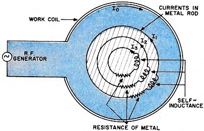
Fig. 6 - Cross-section of currents in rod.
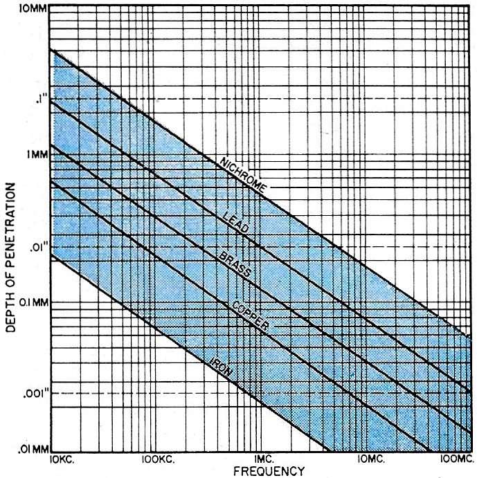
Fig. 7 - Depth of penetration for metals. To show how the skin effect works for the smooth rod used as an example in Fig. 5, a simplified electrical presentation of the currents in the metal is shown in the cross-section drawing of Fig. 6. This shows that the current flowing in each circular path sets up a flux opposing the work coil flux, thereby acting as an electromagnetic shield for the material inside it. For this reason the flux in the inner concentric paths is reduced exponentially, which demonstrates why flux, eddy current, and the consequent heating is greatest on the surface of the work piece. The "depth of penetration" is the point at which the current density is about 37% of its value at the outside surface of the work piece. The actual values of "depth of penetration" for various metals at frequencies ranging from 10,000 cps to 100 mc. are shown in the graph of Fig. 7. By proper selection of frequency it is possible to determine accurately the depth to which the metal should be heated as well as the actual skin temperatures. The Frequency Problem The choice of frequency determines the depth of penetration as indicated in Fig. 7. In practice, frequencies ranging from those used for power transmission to high radio frequencies are employed. In addition to the effect on the work piece, selection of the right frequency must be considered along with efficiency, complexity, and cost when designing the generating equipment. Every radio ham knows that it usually costs more to put the same power on the air in the 2-meter band than in the 80-meter band. At the higher frequencies tubes become less efficient, losses inside the generating equipment rise, and the amount of spuriously radiated power increases. This latter type of loss is costly in two ways. First, any r.f. power that is radiated into the surrounding atmosphere is lost to the work coil; second and of more importance, radiating energy interferes with other services such as communication or radar. In most machines the exact frequency is not controlled by a crystal oscillator but depends on the tuning of the power oscillator and stable, known frequencies are difficult to maintain. This is particularly true where frequencies are adjusted for a certain work piece during one production run but must be changed during the next run. Radiation at frequencies which can interfere with aircraft beacons, communications, and similar services is possible. In addition, the harmonics generated by high-power induction heating machines may reach into the TV, FM, v.h.f., and other frequency bands. To avoid interference with other services, the FCC has issued strict limits on permissible radiation from industrial and medical equipment. For operation at any frequency except 27.55 mc., the maximum radiated field permitted is 10 microvolts-per-meter at a distance of one mile. The 27.55 mc. band is set aside as an experimental and industrial frequency allocation within which these limits need not be observed. The radiation limits apply not merely to the fundamental but also to all harmonic and subharmonic signals which might be due to induction heating machines. To insure compliance with FCC regulations each induction heating machine must be tested, signal strength readings must be taken, and a certificate of approval obtained from the engineering firm doing the testing. In many installations, especially at the lower frequencies, radiation does not present a problem, but where higher frequencies are used shielded work booths and similar devices must occasionally be employed to avoid interference.
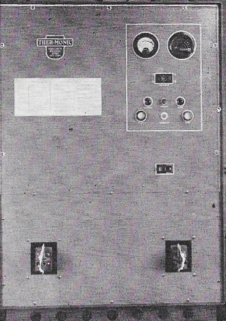
Fig. 8. Photo above shows the front panel of a 7.5-kw. induction heating generator. Note simplicity of the controls required. How serious the interference problem can be is shown in a recent case history of persistent interference with an aircraft localizer beacon. The interference was finally traced, by an FCC mobile unit, to an insufficiently shielded induction heating installation. Makers of induction heating machines are now aware of the radiation problem and usually have every new model checked for radiation before leaving their plants. Some of our readers who have experience in building transmitters may ask why crystal-controlled induction heating machines are not in wide use. Actually most manufacturers make at least one type of crystal-controlled unit, operating at 27.55 mc., which does not require extensive external shielding. For a general-purpose induction heating machine, such as the 7.5 kw. unit shown in Fig. 8, the nominal frequency is 450 kc. As the work coils are changed, as more or less power is demanded, the oscillator frequency will normally change somewhat. There is little point in keeping the frequency absolutely fixed by means of a low power crystal oscillator and a chain of power amplifiers, each of which merely wastes d.c. power. Instead, the tank circuit can be adjusted for maximum power output for each individual work piece. To minimize the external shielding required, the entire generator is housed in a grounded, electrically bonded cabinet. The Basic Circuit The 7.5 kw. induction heating generator just mentioned is probably typical of the medium-sized machines and its circuit, shown in Fig. 11, will be of interest to our technically minded readers. One unusual feature of this oscillator is the fact that the plate is grounded while the grid and cathode receive a high negative voltage. Part of the r.f. signal developed across the plate tank circuit is fed back to the grid through the tickler coil. R1 and C1 make up the grid-leak network. R2 limits grid current during the positive portion of the cycle. The working r.f. energy is coupled by transformer T1 to the work coil and its load. If the plate were at a high d.c. voltage, a coupling capacitor would be required or the transformer would have to have high-voltage d.c. insulation. The simplicity of the basic circuit of Fig. 11 is shown by the physical appearance of the r.f. power panel of the Thermonic model 750 generator, Fig. 8. Fig. 12 is a simplified diagram of a 20 kw. G-E induction heating generator. Here a coupling capacitor isolates the work coil from the d.c. power and the work coil forms a part of the oscillator tank circuit. In addition to the r.f. oscillator circuit there is a d.c. supply to furnish the necessary power.
Fig. 9. This illustration shows typical work coils that are employed in induction heating equipment. (A) shows some of the common shapes used. (B) illustrates how special shaping is used to fit the metal sections that are to be heated. (C) shows placement of work coils with respect to work pieces.
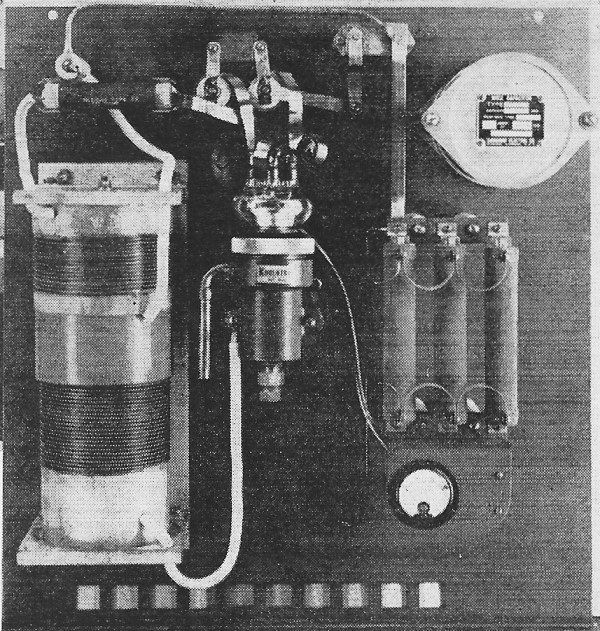
Fig. 10. Interior view of generator of Fig. 8. showing the r.f. oscillator.
Fig. 11. Here is the basic circuit that is employed in the 7.5-kw. induction heating unit described in text.
Fig. 12. Simplified diagram of a 20-kilowatt induction healing generator. The control circuits to regulate the "on" time and to protect the equipment in case of failure of the cooling system, are quite a plant in themselves. The 7.5 kw. generator shown in Fig. 8 requires 300 cubic feet of forced-air cooling per minute and 8 gallons of water at a pressure of 40-45 psi. The water is used to cool the transmitting tube and the various power coils and then the heated water gives off its heat to the cooling air. This means that an internal pump circulates water to the hot points in the system and then, just like in an automobile, the water is cooled down again by passing through a radiator while a fan blows cool air through it. This cooling system removes the d.c. and filament power which is not turned into working r.f. power. The Work Coil Once an induction heating generator is installed, the design of a suitable work coil for the particular application is the most important problem. Since the magnetic field generated by the work coil decreases rapidly with distance, the coil is placed as close as possible to the area to be heated. Therefore, work coils are designed to fit each application. Many work coils are cooled by the main water cooling system and are made of copper tubing or hollow copper fixtures. Some typical shapes for various jobs of hardening, brazing, and soldering are shown in Fig. 9. Note how the shape of the coil determines the shape of the area which is heated. It is possible to heat inside surfaces as long as the work coil can be made small enough to fit into the opening. In industrial practice, once the basic work coil for a particular generator has been designed, special variations are often built by plant technicians who are familiar with induction heating methods. Larger automatic and semi-automatic installations serving continuous production runs usually employ carefully designed and tested work coils, especially if an additional operation such as quenching or bending is part of the heating set-up. Typical of this is an area hardening process where a certain spot is rapidly heated and then sprayed with a cooling fluid or else dropped into a coolant bath. Here the hardening cycle would be automatically controlled by a timer and at the end of the hardening cycle the spray would be turned on for a short period. Repair and Maintenance Many of our readers in the servicing field are wondering if the repair and maintenance of induction heating equipment does not offer a new field for the electronic service technician. A survey of the major manufacturers shows that service is usually handled by their own personnel. Induction heating generators are installed and tested at the customer's plant by the manufacturer's own engineers. After a short instruction period plant maintenance men or plant electricians are usually capable of replacing tubes, fuses, and similar parts by referring to the service manual and possible phone consultation. According to one of the leading manufacturers, service calls by field engineers are quite rare because of the extremely rugged design and ultra-reliable components used in this type of equipment. Much of the hardware inside a typical high- or medium-power generator consists of the cooling system and most maintenance people are capable of repairing leaky plumbing, worn out blower motors, water pumps. There is a place for people with electronics training in the induction heating field, but it is usually as an employee with the manufacturer. Here knowledge of electronics need not exceed amateur radio experience or a general theoretical understanding of radio equipment, but there should be a strong background of metal working, machine shop, and production processes. Jobs in the induction heating field are not too hard to find and most firms are on the lookout for capable electronic technicians.
Posted July 20, 2018 |
|||||||||||||
 |
|||||||||||||
|
|||||||||||||


|
||||||||||||||||||||||||||||||||||||


