|
|||||||||||||
 |
|||||||||||||
The Hall Effect
|
|||||||||||||
Hall effect devices are used not just for magnetic field measurements, but also for for current and power measurements and as function generators, transducers, multipliers, and isolators. The Hall effect, discovered by Edwin Hall, comes into play when a stationary current-carrying conductor is located in a magnetic field, where electrons within the conductor are forced into a distribution that favors one side of the conductor. The result is a difference of potential across the conductor which is directly related to magnetic field strength by a well-defined equation, permitting measurement of the magnetic field. A gaussmeter works on that principle. Since a Hall device's output is proportional to the product of the control current and the magnetic field, and the magnetic field determines the Hall voltage, power can be determined with the devices as well. The Hall Effect
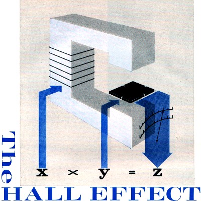
The phenomenon was recognized long ago as a curiosity. New materials are rapidly moving it out of the laboratory and into a growing number of practical devices. By John R. Collins Great progress is being made toward moving a rather ancient principle - the Hall effect - out of the laboratory and into practical use. Electronics exhibits, manufacturers' catalogues, and advertisements display an increasing number of products incorporating Hall devices now available for purchase. And the end is not in sight - new applications appear continually in the literature. Unquestionably there are still more Hall devices on drawing boards than on production lines. While the Hall effect dates back to 1879, it remained a sort of scientific curiosity for more than half a century. With the advance of semiconductor technology, however, it has become possible to make Hall units with the necessary sensitivity, stability, and output. The major emphasis thus far has been on instruments for measuring magnetic fields or determining the magnetic properties of materials. In addition, however, Hall devices are used for current and power measurements and as function generators, transducers, multipliers, and isolators. The Hall effect refers to the influence a magnetic field has on a stationary current-carrying conductor. Perhaps the easiest way to visualize the effect is by thinking of the familiar motor principle. A current-carrying conductor which is cut by a magnetic field will be subjected to a thrust which will cause it to move at right angles to both the direction of the current and the direction of the magnetic field. This principle is the basis of operation of d.c. motors and the D'Arsonval meter movement. A natural question is, what happens if the conductor is restrained so that it is not free to move? Edward H. Hall found the answer through his experiments at Johns Hopkins University more than 80 years ago. Using a thin strip of gold leaf as a conductor, Hall showed that a difference in potential ("Hall voltage output" in the diagrams) will appear across opposite edges of the strip under these conditions. This is illustrated in Fig. 2A. The explanation of the effect lies, of course, in the deflection of electrons in the current stream to one side of the conductor by the influence of the magnetic field, as shown in Fig. 2B. The same sort of deflection may be observed in a magnetic-deflection type cathode-ray tube. In some semiconductors, positive charges ("holes") are the majority carriers, and these are also deflected by the magnetic field. The concentration of like charges at one edge of the conductor produces a difference in potential as would be expected. This is called the Hall voltage.
Fig. 1 - Flat probe by Radio Frequency Labs used to detect transverse fields. InAs element is embedded near blade tip.
Fig. 2 - (A) Hall voltage develops in the conductive strip. (B) Path of deflected electron. Direction of flux is into page. The magnitude of the Hall voltage is directly related to the strength of the magnetic field. As electrons are deflected to one side, the negative charge thus produced tends to oppose the movement of more electrons to that edge. A condition of equilibrium is reached when this repelling force exactly balances the impelling force of the field's magnetic strength. The relationship among the several factors which determine the Hall voltage is expressed by the following formula: Vh = Rh/d X I X B X sin θ. Vh = Hall voltage in volts, Rh = Hall coefficient (described below), I = current in amperes, B = magnetic flux density in gauss, d = thickness of conductor in centimeters, and θ = angle between I and B. In the usual case, where I and B are at an angle of 90° with respect to each other, the sine of θ is 1 and can be ignored. Materials Early experiments with the Hall effect were limited because of the lack of suitable materials and although many different metals were tried (including antimony, cobalt, sodium, and zinc), the results were far from satisfactory. Resistance of the materials was low, making it difficult to obtain a Hall voltage large enough for practical purposes. When materials of higher resistance were used, the efficiency declined to such an extent that the device became virtually useless. Experiments show that there are two factors which determine the suitability of materials for Hall effect use. First, the mobility of the charge carriers (either electrons or holes) must be high. This is obviously important since carrier mobility determines the response to an applied force and hence the sensitivity of the device. High mobility, however, tends to reduce the resistance of the device so that impedance matching becomes a serious problem. The best way to overcome this difficulty without lowering the efficiency is to reduce the number of carriers by purifying the material. These considerations are expressed in the following formula for the Hall coefficient: Rh = μ/ς where μ is the mobility, a measure of drift velocity of the carriers, expressed in terms of drift per centimeter per second for a potential gradient in volts per centimeter, and ς is a measure of the concentration of the carriers per cubic centimeter of the material. The Hall coefficient thus serves as a figure of merit in selecting materials for use in Hall devices. Indium antimonide (InSb) has the greatest carrier mobility and hence the highest efficiency of any material thus far discovered. It is quite temperature-sensitive, however, and this fact has limited its use. Instead, many Hall devices now employ either indium arsenide (InAs) or indium arsenide phosphide (InAsP). These materials have a carrier mobility substantially greater than either germanium or silicon and, while not as efficient as InSb, they are considerably less temperature-dependent than indium antimonide. Hall Generators A Hall generator is a solid-state multiplying device which is designed to produce a Hall output voltage proportional to the product of the control current and the magnetic field. It is constructed by forming semiconductor material into a thin wafer and attaching leads to each of the four sides. Two opposite leads are for conducting the control current, and the other two are the Hall output voltage leads. The wafer is attached to a thin, insulating panel and the unit is encapsulated in epoxy resin. The Hall-voltage formula above shows that the output increases as the thickness of the conducting wafer decreases. It is advantageous, therefore, to make the wafer as thin as mechanical strength will permit. In addition, the panel on which it is mounted should be made thin so as to fit into the small air gaps found in practical equipment. Intermetallic elements, such as InAs and InSb are very brittle, making it difficult to machine them to very thin sizes. A solution to this problem is to vacuum-deposit the material in a thin film on a glass or ferrite substrate and to connect leads to opposite sides before encapsulation. The Helipot Division of Beckman Instruments, Inc. produces units in this manner, depositing InSb in a film only 7 microns (0.00028") thick on a substrate plate 0.012" thick. These units are extremely sensitive because of their thinness and because of the high carrier mobility of InSb. Some will give Hall output voltages of 2 volts per ampere-kilogauss. Deposited-film construction provides a large surface-to-volume ratio which helps dissipate heat - an important factor since InSb, as already mentioned, is extremely temperature-sensitive. The thinness of the film places a limit on the amount of current that can be handled, however, so it is necessary to strike a balance among several variables in order to obtain a sensitive Hall generator which will have reasonable dimensions and still be capable of handling practical currents. Fabrication of Hall generators is a delicate operation which requires careful attention to construction details. One source of error results from improper alignment of the Hall output voltage leads on the edges of the wafer. Unless these are exactly positioned at equipotential points, a voltage will exist between the contact points whenever there is current flow, even with zero magnetic field. The effect, known as the resistive null voltage, can be compensated for by a resistive network, but unless this is done the generator will give false readings and the error will increase with the current. The speed of response of a Hall generator is extremely fast, ranging well into the megacycle region. By itself, however, a Hall generator is an incomplete unit, since a magnetic circuit is needed for its operation. The inherent slowness of magnetic circuits usually limits the final speed which can be attained in Hall circuits.
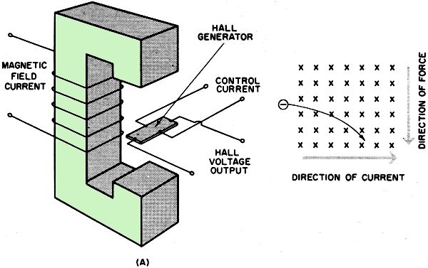
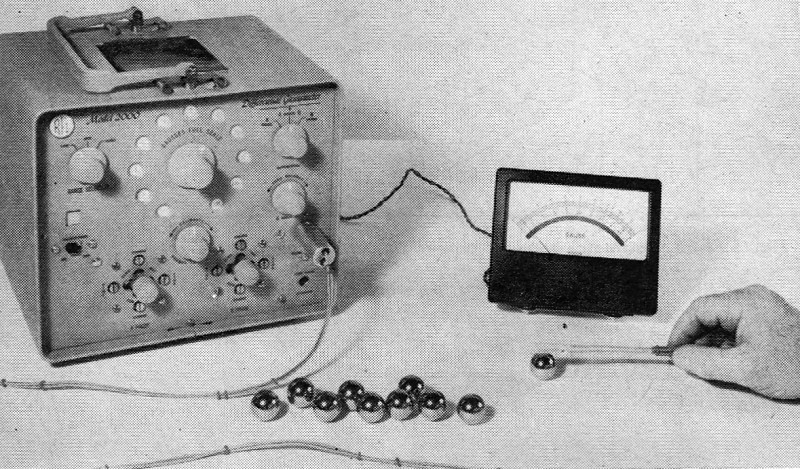
Fig. 3 - Sensitive gaussmeter by Bell measures small fields.
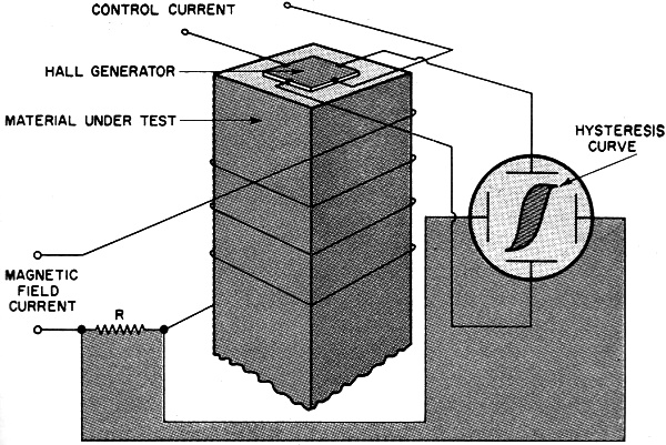
Fig. 4 - Test assembly for tracing hysteresis curve on scope.
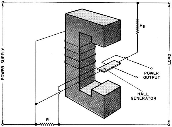
Fig. 5 - Hall wattmeter renders power as product of E and I.
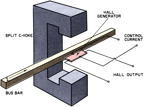
Fig. 6 - Hall element and split C-yoke make clip-on ammeter.
Fig. 7 - An axial gauss meter probe, with element mounted flat at its end, for detecting fields directed toward its tip.
Fig. 8 - Two matched probes are used in this differential gauss meter by RFL. It can detect flaws in magnetic materials.
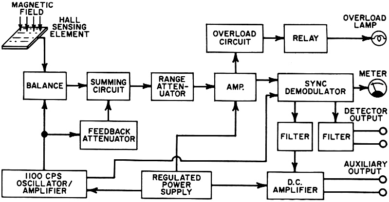
Fig. 9 - How the amplified Bell gaussmeter of Fig. 3 works.
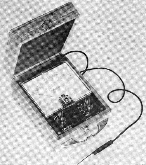
Fig. 10 - A portable gaussmeter by Instruments Systems Corp., with its probe. Gaussmeters One of the most important applications of the Hall generator is detecting and measuring magnetic fields. For this purpose, it has the advantage over more conventional instruments in that relative motion is not needed between the magnetic field and the pickup element. It is only necessary that the control current (which can be either a.c. or d.c.) be a known quantity. Hall-effect gaussmeters are shown in Figs. 3 and 10. Since it is often necessary to measure magnetic flux in narrow air gaps, the Hall generator is usually mounted in a probe which is connected through a cable to the gaussmeter instrument. Various kinds of probes have been developed to meet the different conditions of use. A transverse probe Fig. 1) is used to detect fields directed toward the probe's flat side, while an axial probe (Fig. 7), with a small Hall generator mounted flat at its end, is used for fields directed towards the tip. Probes less than 0.02" thick are available for making measurements in very narrow air gaps. Through the use of a probe, an operator can determine the area where flux density is greatest and, since the Hall output is greatest where the generator element is perpendicular to the magnetic field, it is easy to find the field direction. Information of this kind is especially useful when checking for flux leakage in the vicinity of transformers or relays. For very accurate work, the gauss meter is zeroed while the probe is in a special zero-gauss chamber which shields the sensitive element from the earth's field (about 0.5 gauss) and any stray magnetic fields. Also, standard magnets of known strength are used to calibrate the gaussmeter. A very sensitive gaussmeter with 12 full-scale ranges from 0.1 gauss to 30,000 gauss is shown in Fig. 3 and in block diagram form in Fig. 9. The circuit is entirely transistorized. An oscillator feeds a 1100-cps, 100-ma. control current through the sensing element. In the presence of a magnetic field, the Hall output voltage will be an 1100-cycle voltage which is amplitude-modulated by the magnetic field being measured.
A portion of the oscillator output is fed back into a summing circuit where it is used to cancel out a major portion of the signal caused by the magnetic field. High amplifier gain then permits small changes in field strength to be studied in detail. After amplification, the signal is demodulated to obtain a d.c. or a low-frequency a.c. signal proportional to the magnetic field. This signal deflects the panel meter and may also be used to operate control circuitry or an oscillograph. Gaussmeters of this kind are especially useful for studying small changes in a magnetic field, hence their name "incremental" gaussmeters. Since the signal and the detector are synchronized, the circuit rejects out-of-phase signal components, a factor which tends to reduce the effects of noise. Among other applications, they are useful for evaluation of magnetic ink, tape, and magnetic memories. A different gaussmeter is shown in Fig. 8. It utilizes two matched probes which are mounted parallel to each other at a fixed distance apart. The system is supplied by a 3000-cycle oscillator, and separate constant-current amplifiers furnish the control current to each probe. The current through each element is held constant to insure that its output will be exactly proportional to the magnetic field at that point. The Hall voltage output of one probe is inverted and added to the voltage output of the other - which amounts to subtracting the two outputs. The difference voltage is displayed on the meter, which can be detached from the instrument itself for convenient viewing. Differential voltmeters of this kind are useful for measuring the gradient of the magnetic field in connection with locating and measuring flaws, anomalies, and residual magnetism within ferromagnetic materials. Uniform fields, such as the earth's, do not affect the readings regardless of the position of the probe. It is notable that many sensitive gaussmeters employ a.c. for the control current and thus have an a.c. Hall output voltage. The advantage is that a.c. is easier to maintain at a constant level since it is not subject to the drift problem encountered in d.c. Also, such a.c. voltages are much easier to amplify. While many Hall-effect gaussmeters are employed for intermittent measurements, they are also useful in continuous applications. One of the most demanding applications is the monitoring and controlling of the magnetic field of a mass spectrometer. The field must be maintained at an extremely constant level in order to make possible the delicate analysis carried on by a mass spectrometer. Even when the voltage of the electromagnet power supply is kept at a constant level, the current and the magnetic field may vary because of resistance changes due to temperature fluctuations. A Hall-effect gaussmeter is used to monitor the field and to act as the sensing element in an automatic control loop. Hysteresis Curve Tracer A special adaptation of the Hall effect is in the measurement of the hysteresis of magnetic materials. The key to the way a magnetic core will perform in a particular application is its hysteresis curve, which shows how the flux density in the core varies with the cycling of an a.c. magnetic field. A fast, accurate means of plotting the hysteresis curve is a necessity for development work and in manufacturing many kinds of magnetic devices. Hall generators are especially useful for such analysis because they measure the instantaneous field without any time lag. The hysteresis loop can be displayed on an oscilloscope. The basic elements of such a curve tracer are shown in Fig. 4. The magnetic core to be tested is placed in the center of a coil through which is passed an a.c. current which is in phase with the control current. A voltage drop is obtained by means of a resistor inserted in the path of the winding and the voltage thus obtained is applied to the horizontal plates of the oscilloscope. The Hall device is placed in contact with the magnetic test material so that the magnetic field will be perpendicular to it. The Hall voltage thus derived is applied to the vertical plates of the oscilloscope. The result will be a typical hysteresis curve. Power Measurement A Hall generator, as mentioned before, is fundamentally a multiplying device, producing an output that is proportional to the product of the control current and the magnetic field. Since power is determined by the product of current and voltage (P = E x I), it is only necessary to have the control current proportional to the circuit voltage and the magnetic field proportional to the circuit current in order to obtain a Hall voltage proportional to the circuit power. A generalized wattmeter circuit employing a Hall generator is shown in Fig. 5. A shunt, R, is provided so that only a portion of the circuit current flows through the coil and a series dropping resistor, Rs, limits the voltage applied to the Hall generator. The selection of values for the two resistors depends, of course, on the amount of power involved. In a practical wattmeter capable of measuring power in a.c. circuits at frequencies from 50 to 500 cps, the magnetic field is provided by a coil in the line circuit, and the control current is obtained from a stepdown transformer connected across the load terminals. The output is a double-frequency wave superimposed upon d.c. The double-frequency component is proportional to volt-amperes while the d.c. component is proportional to watts. The Hall effect is extremely fast and if an oscilloscope is used as the output device instead of a conventional meter, it is possible to show instantaneous power. This is useful in studying transients which occur as fault currents when a circuit has been broken or interrupted. Hall-Effect Ammeter A hook-on ammeter is an instrument which can be used to measure current in a conductor when it is in close proximity to or hooked onto the conductor. The fact that the circuit does not have to be opened to allow the meter to be inserted in the current path is a great advantage, especially for measuring high bus-bar currents, and a convenience that saves both time and effort with a current of any magnitude. By using a split C-yoke with a Hall generator (Fig. 6) in the air gap, a hook-on ammeter can be made which overcomes many of the difficulties in some other types of instruments. The control current, which can be either a.c. or d.c., is maintained at a constant level. The magnetic field which surrounds the bus bar supplies the field for the Hall generator. Since this field is proportional to the current in the bus bar, the Hall output voltage will also be proportional to the bus-bar current.
Other Applications Many other ways of utilizing Hall generators have been devised. Some are already in limited use, many are still theoretical. A frequency doubler, for example, can be constructed using a Hall generator. If the same a.c. source is used for both the control current and the magnetic field, the Hall-output voltage will have an a.c. component with a frequency twice the frequency of the input. Similarly, the Hall generator can be used as a device for squaring functions. If the magnetic field and the control current are both driven by the same signal source, the output will be proportional to the square of the input. The Hall generator can also be used as a function generator in an analog computer. In the discussion above, it was pointed out that the Hall output voltage is proportional to the product of the control current, the magnetic field, and the sine of the angle between I and B. Accordingly, if the Hall generator is rotated in the magnetic field, it will produce a sine wave (or a cosine wave, depending on the point of reference). Conventional function generators produce outputs whose amplitudes depend on the rate at which magnetic lines of force are cut by a conductor. The output of the Hall generator is independent of the speed of rotation, however, and it is therefore especially well adapted for very-low-frequency operation. When very small d.c. signals must be measured, it is often convenient to convert them first to a.c., so that they can be readily amplified and to eliminate drift problems. A Hall generator is useful for this operation, which is known as "chopping." An a.c. magnetic field is employed, and the low-level d.c. voltage is impressed across the Hall control terminals. The output of the generator is then an a.c. signal that is equal to the product of two quantities: the magnetic field and the control current resulting from the d.c. voltage. Another application in which Hall generators show promise is as isolators in microwave circuits. An isolator is a four-terminal, unidirectional, transmission device. Electron tubes and transistors used as amplifiers are examples of isolators, since they operate in one direction only. A tunnel diode, on the other hand, is a two-terminal, bidirectional device. The fact that tunnel diodes have common input and output terminals makes it difficult to build multi-stage amplifiers in which they are employed. Effort is currently being devoted to using Hall devices in conjunction with tunnel diodes. If it is successful, the usefulness of both devices will be broadened by another configuration providing the necessary isolation of the input and output circuits.
Posted October 6, 2023 |
|||||||||||||
 |
|||||||||||||
|
|||||||||||||


|
||||||||||||||||||||||||||||||||||||


