|
|||||||||||||
 |
|||||||||||||
Grounding Techniques
|
|||||||||||||
Proper grounding often makes the difference between success and failure in a circuit - from DC to light. I recently fix an intermittent hum in a vintage cassette tape deck by discovering and repairing a cold factory solder joint on the shield connection of an input RCA plug. Improperly grounded shields in electronic circuits cause coupling and interference issues, addressed via single-point or multi-point grounding based on interference frequencies, cable length, and circuit sensitivity to high- or low-impedance fields. Single-point grounding suits short shields (L/λ < 0.15, where L is length and λ is wavelength of highest frequency), with each insulated shield grounded individually, effective for low frequencies like audio but failing against magnetic/electrostatic coupling at longer lengths. Multi-point grounding is recommended for L/λ > 0.15, at 0.15λ intervals or both ends, excelling against electrostatic coupling (ideal for RF) but vulnerable to ground currents. Guidelines include avoiding shields as signal returns, using twisted pairs or balanced lines with individual insulated shields, terminating coaxials in characteristic impedance, and employing shielding shells, backshells, bonding halos, or interlacing straps (≤1.5-inch wide copper) at connectors for low-impedance bonds. Minimize pigtails, ensure metal-to-metal continuity across connectors, and ground both sides to prevent noise entry via short paths. Grounding Techniques
Martin Mirsky received his BEE degree from Pratt Institute in 1957 and attended Ohio Sate University Graduate School. In 1961 he joined Filtron and is presently associate director of the Interference Laboratory. Prior to that he was employed by the Wright-Patterson Air Development Center as an RFI/ EMC specialist. He has published several papers on interference.
Saul Bernstein received his B5 degree from Hofstra University in 1957. Until 1959 he was employed by General Electric Co. as an EMI specialist in radar and guidance systems. Since then he has been manager of the Filtron Company's Test Div. By Saul Bernstein Improperly grounded shields can cause coupling and interference problems in sensitive electronic circuits. Shields can be single- or multi-point grounded. The problem of electrical compatibility in a complex electrical or electronics system is, in many cases, dependent on the treatment of the shielding and the grounding of the wire shields. Injudicious application of a grounded shield to a wire may cause coupling problems that otherwise would not exist. Grounding of the shields may be accomplished as single-point or multi-point grounding. Factors that influence the selection of single-point or multi-point grounding include the interference signal frequencies involved, the length of the transmission line, and the relative sensitivity of the circuit to high- or low-impedance fields. The two grounding methods are more completely defined as follows: Single-point shield grounding. For multi-lead systems, each shield may be grounded at a different physical point as long as individual shields are insulated from each other. Single-point grounding is more effective than multi-point shield grounding only for short shield lengths. Single-point grounding is ineffective in reducing magnetic or electrostatic coupling when conductor length-to-wavelength (L/λ) ratios are greater than 0.15; where the wavelength is that of the highest frequency to be used (or the highest frequency interference to be expected) on the wire or on the system.
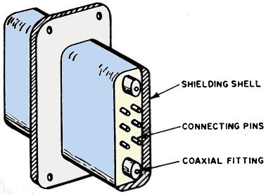
Fig. 1 - Connector with pins enclosed by shielding shell.
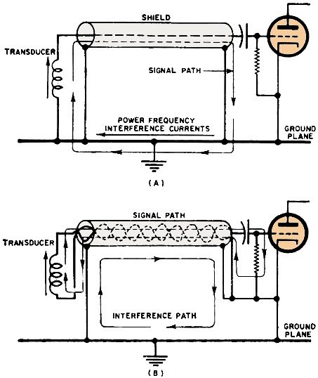
Fig. 2 - (A) Multipoint shield grounds couple noise into signal circuits; twisted pair (B) reduces interference.
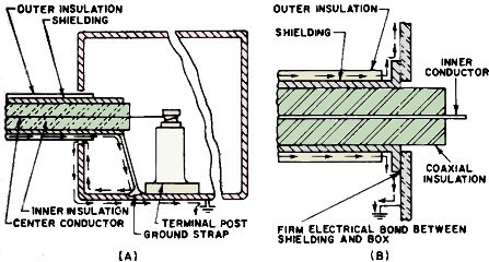
Fig. 3 - (A) Shows the incorrect method of introducing shielded cable into junction box, (B) is the right way.
Fig. 4 - Cable shield bonding for chassis connectors (A) when receptacles are on front panel, and (B) are on rear of chassis.
Fig. 5 - Poor bonds permit noise to enter equipment.
Fig. 6 - When bonding halos are used to terminate shields in a harness, they minimize the termination's impedance.
Fig. 7 - An interlacing strap is the best common ground. Multi-point shield grounding. For L/λ ratios greater than 0.15, multi-point grounding at intervals of 0.15, is recommended, for the shield can act as an antenna that is relatively efficient at L/λ when one end is grounded. When grounding the shield at intervals of 0.15 is impractical, shields should be grounded at each end. Multi-point shield grounding is effective in reducing all types of electrostatic coupling, but is subject to failure if large ground currents exist. In general, multi-point shield grounding solves most problems, but in audio circuits single-point grounding may be more effective because of a ground-current problem. General Considerations Proper cable installation is essential if interference difficulties are to be avoided. Assuming proper grounding techniques have been employed, the following guidelines for good signal cable practice should be observed: 1. Shields should not be used for signal returns. 2. All signal circuits, including signal ground returns, should be individually shielded and have insulating sleeves or coverings over the shields. Balanced signal circuits should use twisted pairs or a balanced coaxial line with a common shield. Where multi-conductor twisted-pair cables that have individual shields as well as a common shield are used, all shields should be insulated from one another within the cable. 3. Coaxial cables should, in all cases, be terminated in their characteristic impedance. 4. On shielded cables in harnesses, where a common shield ground must be utilized, a clamp or shielded and grounded backshell should be used to ground all shields to the connector body. This should be done in addition to connecting the shields to ground through one or more connector pins. 5. Coaxial cables carrying high-level energy should not be bundled with unshielded cables or with shielded cables carrying low-level signals. Although the characteristic impedance of the cable or signal circuit will normally be quite low, the shield circuit impedance may become appreciable if the shield becomes open-ended or electrically long. This reduces shield effectiveness. 6. Shields should be grounded on both sides of a connector to avoid discontinuity; if not possible, the shield should be carried across the connector through a connector pin. 7. Grounding a number of conductor shields by means of a single wire to a connector ground pin should be avoided, particularly if the shield-to-connector or connector-to-ground lead length exceeds one inch, or where different circuits that may interact are involved. Such a ground lead is a common-impedance element across which interference voltages can be developed and transferred from one circuit to another. Connectors Great care must be taken at connectors if impedance characteristics and shielding integrity are to be maintained. A shielding shell should be used to shield the individual pins of a connector. A well-designed connector has a shielding shell enclosing its connecting points (Fig. 1) . The shells of multi-pin connectors should be connected to the shield. Coaxial lines should be terminated in shielded pins. Pigtail connections for coaxial lines are undesirable since they permit r.f. leakage. Cable Shield Grounding Each shield circuit should be carried individually; each should be electrically continuous and grounded at both ends. In the case of long cable shield runs, bonding of shields at intermediate terminals or locations will reduce impedance of the shields to ground, rendering the shielded circuits less susceptible to radiated or induced interference. Individual shields should not be electrically joined together so that one shield carries the r.f. currents of another. To obtain minimum r.f. shielding from shielded wires or coaxial lines, it is necessary to bond them effectively to the ground plane. For a low-impedance r.f. connection, the shortest length of connecting strap or jumper that is mechanically practical should be used. If coaxial cables are used to transmit r.f. signals, they should be grounded at both the sending and receiving ends. Normal coaxial connectors are adequate for this purpose: pigtail connections should be avoided. In applications where twisted -pair cables are used, the shield should be grounded at each end and the circuit return path should be floating (single -point grounding) . Bonding and grounding techniques employed should comply with standard good installation practice. Both multi-point and single-point ground systems offer singular design features. For electronic and electrical systems distributed over a large area, multi-point shield grounding for interference control is superior. The multi-point approach allows short ground connections, provides a low-impedance ground- return circuit, and improves the effectiveness of filter installations. While multiple-ground circuits are recommended for r.f. applications, there are some circumstances, primarily in low-frequency, low-level work with audio or servo amplifiers, in which single-point grounding is necessary. When a shielded cable in a sensitive circuit is grounded at both ends for the return circuit, power-frequency currents in the ground plane can induce audio frequency interference (Fig. 2A) . Therefore, single-point grounding may be the best approach where large a.c. currents flowing in the ground plane may couple into very sensitive low-frequency circuits. To provide extra protection, a shielded twisted Hair should he used (Fig. 2B). The shield should be grounded at both ends; the signal return lead only at one end. Because of multiple grounding of the shield, magnetic fields may be coupled into the shield by conduction or induction. The twisted leads reduce magnetic susceptibility because of field cancellation. Reducing Interference Serious interference problems arise when shielded wires or coaxial cables are not properly terminated at the connector. It is important that the connector be properly grounded. The direct bond for this ground can be achieved by maintaining clean metal-to-metal contact between the connector and equipment housing. In those cases where a large number of individual shields from shielded wires must be connected to ground, it is recommended that the halo or shielded backshell technique be used. The exposed unshielded leads should be as short as possible to reduce electrical coupling between conductors. Interference is caused when a shielded cable is run into a completely sealed box, but is grounded internally. The correct way to install a shielded ri. cable is to run the shield well inside the connector and bond it around the connector shell. The arrows in Fig. 3A show the path that any signal or interference that is picked up on the outer surface of the shielding must follow to return to ground. The currents around the loop generate a field in the enclosed box, as do coupling loops used with resonant cavities. Fig. 3B shows the correct method of introducing shielded cables into a box where shielding must be maintained. Interference currents may be carried when a shielded r.f. cable entering an enclosure has its shield stripped back to form a grounding pigtail. Such pigtails should therefore be avoided. If it is absolutely necessary to use a pigtail it should be kept as short as possible and soldered to provide a ground without breaking the shield. The pigtail should also maintain continuity of the shield (through a pin in the connector) to a continuation of the shield inside the enclosure. The cable r.f. shield is a part of the complete shielding enclosure. Care should he taken to insure there are no openings through which airborne noise can enter. Electric plugs and receptacles are usually mounted on the front and/or rear of the equipment chassis or on the mounting base. If electrical receptacles are on the front of the case, the plugs should be separate units. Shield grounds should be made in accordance with Fig. 4A. If electric plugs and receptacles are placed at the rear of the case one unit should at least be securely attached to the case or chassis; the other separate or securely attached to the mounting base. Shield grounds should be made in accordance with Fig. 4B. Two poor methods of grounding cable shields are shown in Fig. 5. These methods are not recommended because their use permits interfering signals to enter the equipment. In cases where a common shield -ground must be employed, such as on multi- shielded cables or harnesses having a large number of individually shielded circuits, a clamp. bus. or shielded backshell should be used to ground all shields to the connector body: this in addition to grounding them through one or more of the connector pins. The common ground should be avoided when the shield-to-connector or connector-to-ground lead length exceeds one inch, or when current circuits that may interact are involved. To prevent discontinuity of the shield because of possible disconnect at intermediate connectors, shields should be grounded to the structure on both sides of the connector. If this isn't possible, the ground should be carried across the connector or through a conductor pin. Cable Shield Bonding Shields should be terminated no further than 0.25 inch from the ends of the lines they are shielding. Bonding halos, shielded back shells, or interlacing straps should be used to terminate the shields and to minimize the impedance of the shield termination (Fig. 6) . Shields should be connected to the ground plane by 1.5 inches or less of 0.25- or 0.5-inch wide tin-plated copper strap. The halo technique is acceptable only when a few wires are involved. The interlacing strap or shielded backshell method should be used for a common shield ground in multi-shielded cables and in harnesses that have a large number of individual shields. The interlacing strap should be at least 0.25-inch wide by 0.012-inch thick and be bonded securely to the connector. This is shown in (Fig. 7). Coaxial fittings should be kept tight at all times not only to provide a good impedance match but to eliminate loose connections that may result in rectification of interference energy at the fittings. Again, the resulting d.c. voltage may interfere with circuit operation by imposing an undesired bias signal at the circuit's input; or, in the case of power measurements, cause an erroneous wattmeter reading. For these same reasons, shielding or bonding clamps that may be part of the fittings should also be kept tight. Soldered fittings are recommended, particularly at terminations of shielding and braid. |
|||||||||||||
 |
|||||||||||||
|
|||||||||||||


|
||||||||||||||||||||||||||||||||||||


