|
|||||||||||||
 |
|||||||||||||
Designs for Log-Periodic FM and TV Antennas
|
|||||||||||||
Log-periodic dipole array (LPDA) antennas have been a favorite of homeowners and hobbyists since they were first invented back in the late 1950s by Dwight Isbell and Raymond DuHamel at the University of Illinois. In this 1967 Electronics World magazine article, Harold D. Pruett, an assistant physics professor at Colorado State University, outlines DIY zig-zag designs for FM and TV reception, costing under $5 in materials. The FM-only and VHF TV-FM antennas provide 10-12 dB gain, 5° beamwidths, and over 20 dB front-to-back ratios, enhancing signal-to-noise by focusing on transmitters and rejecting noise, multipath distortion, FM stereo hiss, and TV "snow" or ghosts. LPDAs achieve frequency-independent performance across 88-108 MHz FM and 54-216 MHz VHF TV via a scale factor (τ ≈ 0.8-0.9) relating successive half-wave dipole lengths and spacings, with the shortest element at the apex (resonance: f = 5905/ln inches/MHz). Constructed on 1x2 furring strip frames for planar or pyramidal setups, aluminum wire forms vee elements strung between nails, matching 300-ohm twin-lead without a centerline. Tests show reliable 70-130 mile FM stereo and TV reception, outperforming some commercial units. Designs for Log-Periodic FM and TV Antennas
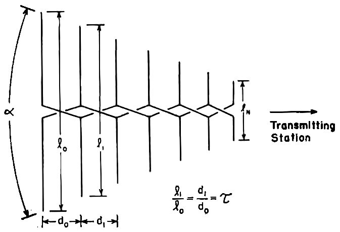
Fig. 1 - Schematic configuration of log-periodic antenna. By Harold D. Pruett, An FM-only and FM-TV antenna are described with gains of 10-12 dB, beamwidths of about 5°, and front-to-back ratios greater than 20 dB. The importance importance of a good antenna for satisfactory reception of FM- stereo or color-TV cannot be over-emphasized. Unsatisfactory reception is often blamed on the receiver but, in many cases, the difficulty is that the antenna is not providing a large enough signal or is picking up signals from undesired directions. Low signal levels result in a high background noise level in the case of FM stereo or "snow" in the case of a TV picture. Signals from undesired directions produce multipath distortion or "ghosts" for the same two systems, respectively. In this article the role of the antenna as well as some details on the log-periodic antenna will be discussed. Plans are included for constructing two such antennas, one for FM only and the other for both TV and FM. These antennas will provide both an adequate signal level and enough discrimination against signals from undesired directions for most reception areas. Cost of materials for constructing either of the two antennas is less than $5.00, materials are readily available, and no special skills or tools are needed.
Fig. 2 - Arrangement employed in the zig-zag LPDA antenna.
Fig. 3 - Side view of the pyramidal log-periodic design shows how upper and lower dipole supports are oriented. The shortest dipole element is near apex which points to transmitter.
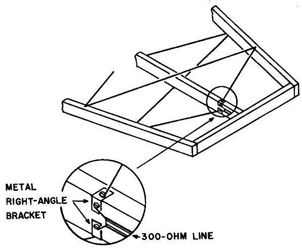
Fig. 4 - Wood frame used to support wire zig-zag FM antenna.
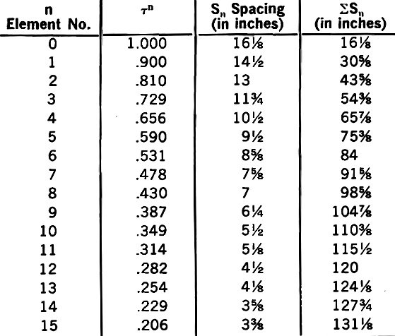
Table 1 - Dimensions to be used for the FM-only antenna.
Table 2 - Dimensions to be used for v.h.f. TV-FM antenna.
Fig. 5 - Method of connecting the final zig-zag element to feeder. Role of the Antenna A brief discussion of the role of an antenna in a receiving system seems appropriate before proceeding to consideration of the log-periodic antenna. In all imaginable situations where information is transmitted, achieving an acceptable signal-to-noise ratio is a primary consideration. A non- directional antenna can pick up and transfer signals to a receiver, but while it is picking up a desired signal from one direction, it is picking up undesired noise from all directions. In contrast, a directional antenna achieves gain in one direction at the expense of gain in all other directions. Since only noise signals would be received from the other directions anyway, you "get something for nothing." Therefore, a directional antenna improves the signal-to-noise ratio in two ways: the signal level is increased and the noise level is reduced by directional discrimination. A measure of the directive gain of a receiving antenna is twice the angular beamwidth, in degrees, at which the power received falls to one-half the maximum value that is obtained when the antenna is aimed directly at the transmitter. The smaller the half -power beamwidth, the higher the gain of the antenna and the more immune it is to reception of noise from directions outside the half-power beamwidth. The similarity between the gain-beamwidth product of an antenna and the gain-bandwidth product of a feedback amplifier should be noted. However, an antenna is a completely passive device in that it cannot amplify a signal. An antenna with directive gain is an array of more elementary antennas, usually half-wave dipoles, phased in such a way that their individual gains add in essentially one direction and cancel in all other directions. Geometric Relations in Log-Periodic Antenna Many readers may wonder why log-periodic dipole array (LPDA) antennas are being widely used in home installations. The primary reason is that an LPDA antenna will cover a wide range of frequencies with nearly constant directive gain and impedance. In addition, its directive gain for a given antenna length is greater than that of many other types of directional antennas. These factors, along with the ease and low cost of constructing LPDA antennas, should indicate the basis for their ever-increasing popularity. The geometric configuration of an LPDA antenna is shown in Fig. 1. The antenna is an array of half-wave dipoles, each of which is formed by two quarter-wave dipoles that are connected alternately to the feeder line. When the length, ln, of a dipole element is related to the frequency received by the equation f = 5905/ln, the element will be a half-wave resonant dipole. In this equation, ln must be expressed in inches and f in MHz. For example, a 59-inch half-wave dipole is resonant at 100 MHz, neglecting the relatively unimportant length-to-diameter and end effects. (These effects may combine to reduce the resonant length by about 2-5% or to a value of about 57 inches. - Editor) Frequency-independent operation of the LPDA antenna is achieved by imposing a condition on the ratio of successive dipole lengths and the spacing between them. As shown in Fig. 1, the ratio condition is l1/l0 = (d1/d0 = r, where r is a constant called the scale factor. The same condition is imposed on all other adjacent dipole lengths and spacings. If ln is the length of an arbitrary dipole, its length is given by ln = l0τn. Similarly, dn = d0τn. If the above condition is met, and if the shortest element of the array is resonant at a frequency somewhat higher than the highest frequency to be received, the gain of the antenna will be constant and independent of frequency. This auxiliary condition is imposed to avoid another kind of end effect, the details of which need not concern us here. As indicated earlier, an antenna with relatively high directive gain is usually an array of properly phased elementary dipoles. In the case of an LPDA antenna, which fits the above description, proper phasing is achieved by alternately connecting the quarter-wave dipoles to the feeder line as shown in Fig. 1, and by controlling the spacing do between adjacent dipoles is the manner described previously. Hal -power beamwidths are approximately 50° for the antennas to be described, and front-to-back ratios are over 20 dB. Frequency Considerations The frequency band from 88 to 108 MHz is allotted to FM. On either side of this are the two v.h.f.-TV bands, one extending from 54 to 88 MHz and the other from 174 to 216 MHz. The u.h.f.-TV band, which is not yet as widely used, extends from 470 to 890 MHz. Television antennas designed prior to the discovery of the log- periodic principle were often made up of two sections, one to cover the lower frequency v.h.f. band and the other the higher frequency u.h.f. band. This is continued with LPDA antennas, but for entirely different reasons. An LPDA antenna could be designed to cover the entire range from 54 to 890 MHz, but the dipoles which resonate in the TV-frequency gaps from 88 to 174 and from 216 to 470 MHz would serve no useful function as far as TV reception is concerned. These dipoles can be omitted in an LPDA design without disturbing the response of the antenna in the frequency ranges of interest and, if this is done, a shorter, less expensive antenna can be manufactured. If the dipoles which resonate in the FM band are omitted, the antenna will not be very satisfactory for FM reception. Anyone contemplating purchase, rather than construction, of an LPDA antenna for both TV and FM reception should examine the unit to see if these dipoles have been omitted. If so, any antenna designed. for FM-only reception is likely to perform better than the so-called dual-purpose TV-FM unit. To illustrate this point, the author found one commercial LPDA antenna that was proclaimed by the manufacturer to be excellent for both TV and FM stereo, but which had less gain on the FM band than a folded dipole! Construction Details There are several antenna configurations in which the dipole elements are located in accordance with the basic log-periodic principle. One such alternate configuration, which lends itself to simple construction, is the zig-zag antenna shown in Fig. 2. In this design, each linear quarter-wave dipole element shown in Fig. 1 is replaced by a "vee"-shaped element such that the perpendicular distance from the centerline of the antenna out to the point of the vee is equal to the quarter-wave length of the linear dipole it replaces. Plans for the home-constructed zig-zag TV-FM antenna were first offered by George Monser in his article "Design for an All-Purpose TV-FM Antenna" in the November 1962 issue of this magazine. Although the antenna described in his article is far from obsolete, the antennas to be described have several advantages over this earlier one. First, the new TV-FM antenna has slightly higher and more uniform gain over the entire v.h.f. TV band, while the FM-only antenna has approximately twice as much gain on the FM band as the original antenna had. Next, the frame for the planar zig-zag configuration used in the present design is easier to construct than the frame used in the original design. The planar zig-zag also requires less vertical space for installation and can be used in an attic with an inexpensive rotor to provide multi-direction reception. Finally, the solder connections to the center feeder line used in the original design have been eliminated, resulting not only in less work, but also in a better impedance match to standard 300-ohm line. The configuration used by Monser is called a pyramidal log-periodic design. When viewed from the side, the supports for the dipole elements are inclined at an angle θ as shown in Fig. 3. If the angle θ is reduced to zero so that the supports are parallel, but spaced a few inches apart, the antenna is called a planar log-periodic antenna. For either the pyramidal or planar configuration, the resonant elements may be linear dipoles, as in Fig. 1, or zig-zag elements as in Fig. 2. The only essential requirement for proper performance is that the inclination angle, θ, should not be larger than the angle a shown in Fig. 1. Although used by Monser in his design, a zig-zag antenna does not require a conducting wire along the centerline when it is connected to a balanced transmission line such as 300-ohm twin-lead. By omitting the centerline wire, distributed capacitance is decreased and the antenna impedance is increased. For example, in a planar zig-zag where the planes of the upper and lower dipole elements are one inch apart, removal of the center wire will increase the impedance from less than 100 ohms to approximately 230 ohms. The 1¾-inch spacing used in the present design results in an impedance slightly higher than that of a 1-inch spacing and an even closer impedance match to standard 300-ohm line. The antennas to be described are intended primarily for mounting in the attic, although mast mounting is possible if the builder is willing to expend a little extra effort in constructing an all-metal version. Except in extreme-fringe reception areas, attic mounting is preferable for both aesthetic and practical reasons. It is doubtful that any rooftop antenna adds to the appearance of a house and, in addition, there are weather problems. Mast- mounted antennas are subject to wind damage and the useful lifetime of standard 300-ohm line is shorter when used outdoors rather than when sheltered by a roof. A wooden frame, constructed from 1 x 2 inch furring strips (actual dimensions are ¾" x 1¾") is used to form and support the dipole elements for both the FM-only and the v.h.f. TV-FM antennas. The shape of the frame shown in Fig. 4 is that of the FM-only antenna; the shape of the TV-FM antenna is similar. Both frames should be constructed with the 2-inch sides of the furring strips oriented vertically. The spacing between the planes of the upper and lower dipole elements would then be 1¾ inches actual. Centerline-to-centerline dimensions indicated symbolically in Fig. 4 are given in tabular form in Tables 1 and 2. The column headed ΣS is the total distance from the large end to the nth element. The total length of the outside member of the frame is the last entry in the ΣS column. Details concerning the antenna frame supports are left to the discretion of the builder since their only purpose is to give structural rigidity. It is best to cut and It is best to cut and completely assemble the antenna framework in an open area to make sure that all the pieces fit together. Most attics are cramped for space and only final assembly should be undertaken there. When construction of the frame is complete, mark the positions of the dots shown in Fig. 4 by using the dimensions given in either Table 1 or 2, depending on which antenna is being built. There will be eight end-point positions for the FM-only antenna and seventeen for the TV-FM antenna. Standing at the rear (large end) of the antenna facing forward, drive nails in the first, third, fifth, etc. positions on the left side of the frame and leave about 34" of the nail protruding. On the right side, drive nails in the second, fourth, sixth, etc. positions. Turn the antenna frame over and then repeat the process. After the frame has been reassembled in the attic, wire to form the dipole elements is strung between the nails. The author used aluminum clothesline wire because it is readily available, but any reasonable sized wire or tubing is satisfactory. Since a center feeder line is not required, the wire can even be covered with insulation except where it is connected to the 300-ohm line. To string the wire, connect one end to the left-rear nail on the top of the antenna, then run the wire over to and around the second nail on the right side, around the third nail on the left side, etc., in zig-zag fashion. The bottom wire is strung in a similar planner, starting with the first nail on the right-hand side. If small wire is used, it should be taut enough so that it doesn't sag, but not so taut that it bends the frame. Vote that the connection to the 300-ohm line is made at the point where the top and bottom wires would otherwise cross the center line for the last time. A method for connecting the final zig-zag element to 300-ohm twin-lead is shown in Fig. 5. As mentioned previously, the only difference between a pyramidal and planar log-periodic antenna is that in the former the dipole supports are inclined at an angle. Both of the antennas whose dimensions are given in Tables 1 and 2 can be constructed in pyramidal form. To do so, two identical frames must be built, one to support the upper dipole elements and the other to support the lower dipole elements. If sufficient attic space is available, the angular separation, 0, should be made equal to a for maximum gain. Approximately 2 dB additional gain can be obtained from the TV-FM antenna with θ = 41° rather than zero. Additional gain can also be obtained from the FM-only antenna by making θ = 13°. An all -metal antenna suitable for mast mounting can be constructed with a little additional work. In a sample model constructed to prove the feasibility of the idea, the author used 10-foot lengths of ½-inch diameter galvanized electrical conduit to serve both as the feeder line and as the structural support for the dipole elements. The wooden frame described earlier is recommended as a jig for locating and forming the dipole elements. Such a jig was used by the author to determine the lengths of the sides of the vees which constitute the dipole elements. Vees were formed from aluminum clothesline wire and the sides were cut about 2 inches longer than required to reach the centerline. Holes were drilled in the conduit where the vees were to be attached. The ends of the vees were inserted through the proper holes and the excess length was bent parallel to the length of the conduit. An eyelet was then formed with the excess length and a metal screw was placed through the eyelet and into a hole drilled in the conduit for anchoring. Ordinary aluminum clothesline wire was used in the feasibility model because it can be easily bent to form the dipole vees. However, rigid aluminum rod is desirable for a mast-mounted antenna that is subject to wind forces. Also, aluminum tubing rather than galvanized conduit is preferable for use as the feeder line because of its lighter weight. As before, either a pyramidal or planar version of the two basic antennas can be constructed. The wooden support shown in Fig. 3, which is used to maintain the angle in a pyramidal version, can actually be metal, since either a short or open-circuit termination is satisfactory. The directive gains of the planar TV-FM and FM-only antennas are 10 and 12 dB above isotropic. Under favorable atmospheric conditions, the author is able to satisfactorily receive two FM stations 130 miles away using a 2.7-microvolt sensitivity (IHF standards) FM tuner and the FM-only antenna. One of the two stations has at radiated power output of only 23.5 kilowatts. FM-stereo stations 70 miles away which have radiated power outputs greater than 10 kilowatts are received satisfactorily all of the time. The FM-only antenna also provides snow-free reception of TV channels 4 through 9 even though the broadcast stations are 70 miles away and the antenna was not designed to cover TV-broadcast frequencies (except channel 6 which is received at 87.5 MHz). As expected, TV reception with the TV-FM antenna is excellent. FM reception with this antenna is not quite as good as with the FM-only antenna, but is satisfactory. |
|||||||||||||
 |
|||||||||||||
|
|||||||||||||


|
||||||||||||||||||||||||||||||||||||


