|
|||||||||||||
 |
|||||||||||||
Computer-Aided Design: Part 1
|
|||||||||||||
The more things change, the more things remain the same. To wit: "When this circuit learns your job, what are you going to do?" asks a poster now appearing widely in subways and buses. That statement appeared in a 1966 issue of Electronics magazine that was reporting on the state of the art in computer-aided design (CAD) of circuits. People are saying the same thing today about Artificial Intelligence (AI). The fact is that AI has been around for as long as there have been machines capable of solving problems, detecting errors, and making suggestions for improvement. If you think maybe high capability CAD is relatively new on the scene, or that early attempts were extremely primitive, disabuse yourself of that notion by reading through the article. Inputs were via punch cards and tape, but the mathematical modeling and matrix functions would make most modern day engineers' eyes roll back in his head. Transistor (BJT and FET) models were composed of 32 parameters, filter models included amplitude, phase, and group delay for multiple topologies, passive components included parasitic values, etc. Designers wanted more capability, of course, but many top-tier companies used in-house or commercially available programs - which would not have been the case if it was not financially beneficial. For context, SPICE came online in 1975, nearly a decade after this article. My first circuit simulator use was with Micro-Cap, while working on my BSEE at the University of Vermont in the late 1980s; it ran on an ATT PC 6300 with an i8085 microprocessor and, 10 MByte hard drive, and a 5-1/4" floppy drive. The Man-Machine Merger
The circuit designer and the computer are headed for a new relationship, say the experts, with the computer as the bright, young, junior partner and the designer as the undisputed boss. By Donald Christiansen, Senior Associate Editor "When this circuit learns your job, what are you going to do?" asks a poster now appearing widely in subways and buses. Intended to alert the public to the need for job retraining to replace obsolete skills, the rhetorical question can strike momentary terror in the heart of the circuit designer, who suddenly wonders if he is designing himself out of a job. Unmistakably, the electronics industry is on the threshold of a new era in circuit design. Directly ahead is the period in which circuits - specifically, computer circuits - designed by an engineer may invade the decision-making area that was once the engineer's exclusive province. The circuits he designs may in turn design new circuits. Faced with this probability, the old-time electronicker, operating solely by intuition and experimentation, has cause for fear, but only if he turns his back on the revolution in progress and ignores the fact that the computer is already working on circuit design. The machine is assisting the engineer by • Performing repetitive calculations. • Evaluating the effects of changes in circuit parameters caused by component tolerances, drift, etc. • Studying the feasibility and cost of circuit optimization. • Simulating component failure. • Developing optimum physical device layouts and optimum circuit interconnection paths. A computer can do a little or a lot; it can be a modest aid or a tremendous help. It can be used at few or many stages of the design process. To decide on the best use of so versatile a tool, computer application consultants at the International Business Machines Corp. suggest that the design process itself be examined first. After that, one can judge which stages of the process should be computerized. The designation of a program depends on this judgment. Unfortunately, confusion is rampant in definitions that relate to computer-aided design. Among terms used frequently and often indiscriminately are these: design synthesis, design automation and computer-aided design. Design synthesis may be thought of as the creation of a set of specifications describing a circuit. Design automation, on the other hand, would include detailed specifications and machine instructions required to fabricate the circuit. And computer-aided design (CAD) indicates the use of a computer at one or more stages of the design process.
The circuit designer and the computer are headed for a new relationship, say the experts, with the computer as the bright, young, junior partner and the designer as the undisputed boss.
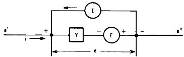
Basic branch for which an ECAP data card is prepared. E and I are voltage and current sources, respectively, e and are branch voltage and current, is the conductance of the passive element, and e' and e" are node to datum voltages.
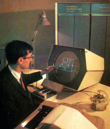
CAD expert Jacob Katzenelson communicates with Project MAC's time-shared computer in an on-line demonstration using the MIT Electronic Systems Laboratory console. Using light pen and typewriter he draws an emitter-coupled multivibrator and assigns component values by typing or sketching characteristics on the display console. Following computer analysis of the circuit, waveforms can be viewed on the console, evaluated, and the circuit returned to the screen for modification. The experiment is carried out by a CAD program called AEDNET, written in MIT's AED-O language.
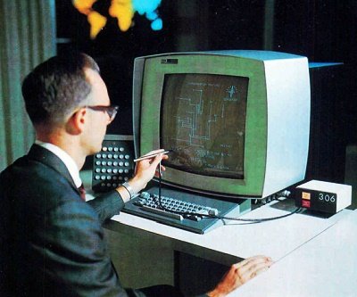
At this console in the IBM World Trade Center in New York, an engineer from the Norden division of United Aircraft instructs an IBM 360 computer in a point-to-point wiring exercise, part of a project Norden has under way to develop on-line methods of man-machine interactions for computer-aided integrated circuit design. The experiment is conducted under an Air Force contract.
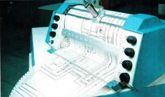
Final design of i-f amplifier at the right is drawn automatically by the plotter.
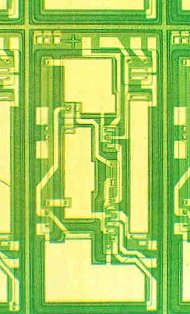
Integrated circuit intermediate-frequency amplifier designed using the Norden-developed CAD program. Components are located and interconnection paths developed with an assist from the computer.
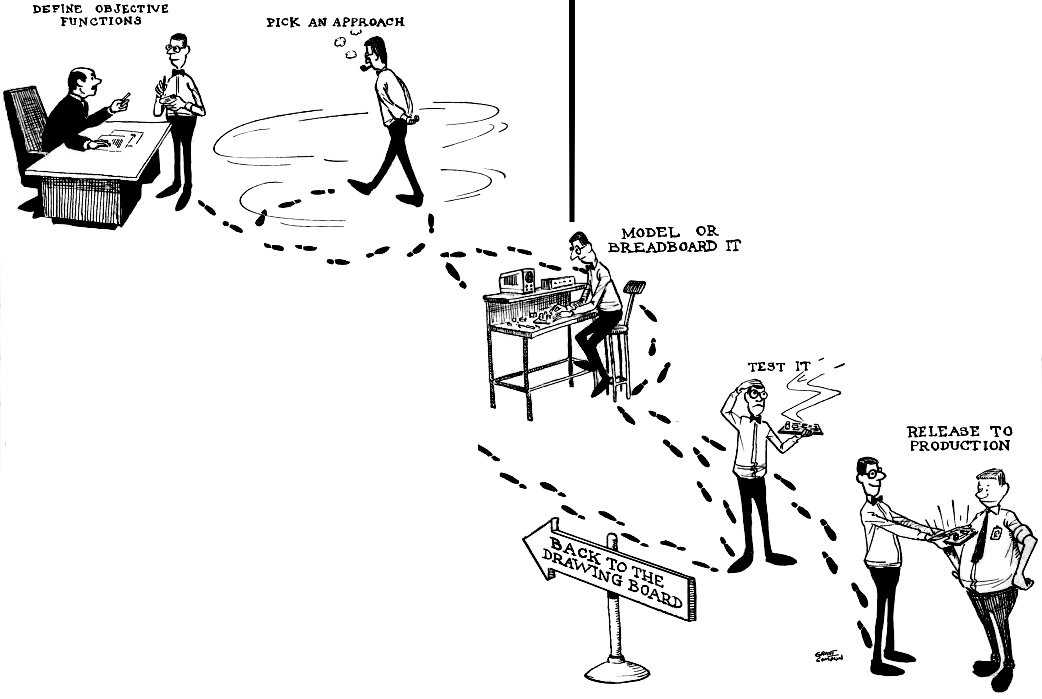
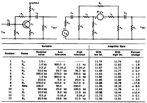
To carry out a sensitivity study of the common emitter amplifier shown here, using the Arinc program, an equivalent circuit, top right, is first developed. Then a description of each element of the equivalent circuit (first five columns in table) is fed to a computer, along with the loop equations and a request for a sensitivity analysis. The computer then provides the results tabulated in the final three columns. The Design Process The designer usually goes through some sequence like this: statement of the problem (or goals), choice of attack, paper design, breadboarding or modeling, optimizing and checking effects of limit devices. At the optimizing stage he diddles potentiometers and otherwise changes parameter values, then checks circuit performance. The process is cut and try. Since his equipment must operate with components that have some production spread, he then searches for limit devices (transistors with high and low-limit beta, for example) plugs them into the breadboard and notes the output. If it is not within spec he'll go back, change some other component or parameter value, and check the result once again. At some point short of perfection he'll freeze the design, knowing full well that he'd better, or the equipment may become obsolete even before the prototype is built.
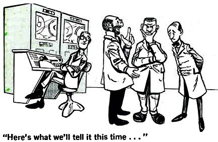
Assigning the repetitive cut-and-try tasks to a computer is the opening wedge to completely automated design engineering. IBM calls this use of a computer the "big slide rule" technique. While helpful, it is limited both in sophistication and payoff. If a computer can simulate a circuit, it can easily perform a given calculation on demand. It is when the computer is called upon to employ its decision-making powers that it plays its most significant role. Then, it can be used to relieve the designer of many intermediate decisions ("Do we have enough gain in this stage, or should we go back and change a resistor?"). Such an approach represents the beginning use of the computer in design synthesis with the computer as a junior partner in the man-computer merger. Design Automation: An Example Since the goal of the design process is to build equipment, the ultimate use of the computer would be its control of the fabrication process for the equipment it has "designed." When design engineering and manufacturing are linked by computer, the process is termed design automation. Carried to its extreme, the technique would mean that equipment could be manufactured directly from the customer's order with little manual engineering. At that point, the computer will be in the main stream of the design function; preparing the engineering paperwork - detailed configurations, machine tool instructions and manufacturing control data - by which the equipment is manufactured. An example of how close design automation is to reality - at least in one area - is the work done by the Norden division of United Aircraft Corp. under an Air Force contract. Using the same basic circuit definition that was used in analyzing the circuit, Norden developed programs that - through a series of man-machine interactions - convert the circuit to a practical integrated circuit format, occupying a minimum of area, with an optimized interconnection pattern. The intermediate-frequency amplifier on page 118 was designed this way. I. Among the Techniques, Dilemmas Galore The computer is a rigid machine, refusing categorically to accept information it cannot comprehend. Communicating with it poses a barrier to the circuit designer because, the experts say, designers know little about programing and programers know less about circuit design. "What shall we tell the computer a circuit is?" is the basic question. Once a model of the circuit has been developed that the computer can assimilate, it is relatively simple to feed the machine a list of trial inputs, parameter values and constraints. In effect, the computer is told: "Here's what we want in, here's what we want out, and here's a trial design - let's see what happens." Model Behavior The accuracy of the circuit model fed to the computer determines how valid the computer analysis is. A bad model yields a doubtful result. Some circuit elements such as resistors are better behaved than others - and can quite readily be represented to the computer. But active devices are tough to model because they're not linear and react to temperature and frequency in a way that is not easily formulated. Research on what constitutes good models has led Cyrus Harbourt, a professor at the University of Texas, to zero in on the narrower, but extremely salient question: "What shall we tell the computer a transistor is?"
A device model can be simple or complex. Complexity permits a more accurate representation of the device over a wide range of circuit conditions. But the use of an overly complex model for the task at hand is time-wasting. Conversely, a simple model is efficient when assigned an appropriate task, but useless when overtaxed. Perhaps the most complex transistor model is the one for NET-1, one of the two widely used general-purpose computer programs. A transistor type is defined for NET-1 by 36 parameters, which can be pre-stored on a library tape, or developed for a new transistor. In contrast, the other major electronic circuit analysis program, ECAP, uses a do-it-yourself device model. ECAP provides resistors, capacitors, inductors, dependent current sources, and a generalized ideal switch. The chief asset of the switching function is that the value of parameters can be altered when selected currents reach predetermined values. Most designers say ECAP is superior when flexibility is sought, but they give the nod to NET-1 for accuracy. Harbourt notes that with NET-1 a complex model must be used even when dealing with problems as simple as a saturating logic circuit. Users of NET-1 express dissatisfaction with the library of device models available to them. Time, effort, and a free interchange among users may resolve the difficulty. Little work has been done on models for the more exotic solid state devices. Even field effect transistor models are hard to come by. Moreover, some phenomena encountered in devices are difficult to model - minority carrier storage time is an example. One of the few companies developing models for offbeat semiconductor devices is Design Automation, Lexington, Mass. The designer is still a long way away from the day when he'll push buttons that feed circuit performance requirements into a computer and get a finished circuit - integrated or otherwise. Today he is more likely to make his inputs in the form of cards or tape bearing data that defines portions of the circuit, operating constraints, and input signal conditions. Outputs for the most part are printed out. Toward the Ideal: NET-1 and ECAP The experts guess that there are anywhere from 200 to 2,000 programs for aiding circuit design. Admittedly, the bulk of them are limited in scope and documentation. Programs proliferate because it's often quicker to develop a new program than to locate, decipher and debug someone else's. Like the ideal secretary, a computer program must be versatile, efficient, accurate, and above all, available. To gain wide acceptance, a program should handle steady state (a-c and d-c) analysis as well as transient analysis. Franklin Kuo, network analysis expert for Bell Telephone Laboratories, Murray Hill, N.J., thinks the perfect program would have a simple input language, handle a wide range of models of physical devices, and provide a nonlinear analysis capability. Kuo says that if automatic parameter modifications were added - it could replace breadboarding - a design engineer couldn't ask for anything more. The two programs which come closest to meeting the ideal requirements are NET-1 and ECAP. NET-1 was developed on the Maniac II computer under the auspices of the Atomic Energy Commission at the Los Alamos Scientific Laboratory of the University of California, Los Alamos, N. M. Since its completion in 1962, the program has been translated into versions for the IBM 7040, 7044, 7090 and 7094 computers, and is used at over 60 commercial, government and university installations here and abroad. One of the chief virtues of NET-1 is that it's easy to use. Specifically, the user need not know how to solve simultaneous nonlinear differential equations, nor manipulate matrix algebra, nor cope with numerical instability. He doesn't even have to know simple programing techniques and, when analyzing a circuit, needn't have the slightest idea how the circuit works. If instructed properly, the computer will deliver an accurate circuit analysis - one which may provide some insight into hazy circuit operation. NET-1 can simulate fixed value resistors, capacitors, inductors and mutual inductive couplings. Additionally, it can handle both junction transistors and diodes, fixed-value voltage sources and several classes of time-dependent voltage sources - including trapezoidal, sinusoidal, exponential and tabular waveshapes. The transistor model for NET-1 requires specification of 36 parameters; the diode model, 13. ECAP, the other major general-purpose program, stemmed from the joint efforts of IBM and the Norden division of United Aircraft. ECAP is written in Fortran for the 1620, 7090 and 7094. Using ECAP, the designer develops an equivalent circuit based on the circuit he plans to study. In it, he is free to use any representation of a transistor or diode that he chooses, providing it is modeled with conventional circuit elements. In ECAP, the matrix approach is fundamental and information on basic network branches are key entries to the computer. Each branch comprises three network elements, pictured on the next page - a passive element (resistor, capacitor or inductor) a voltage source and a current source. Branch terminations are called nodes. Cards, representing the branches of the equivalent circuit, are punched. Each branch card contains data that tells where the nodes are connected, identifies assumed direction of current flow, and provides the value of voltage, current and passive element. The input to each card is user-oriented; no translational language is needed. ECAP can perform d-c, a-c and transient analysis and has options for sensitivity, standard deviation and worst-case analysis. Arinc Program The Arinc Research Corp. at Santa Ana, Calif., has a general-purpose program that can be used without knowledge of either Fortran or machine language. A circuit to be analyzed is described by a linear equivalent circuit for which n simultaneous equations in n unknowns are written. A source deck of punched cards contains the circuit equations in standard matrix notation as well as equations describing the desired output solutions. Parameter data for the Arinc program goes on a separate deck of punched cards. Each card represents one circuit element, and contains such data as nominal value, tolerance limits, temperature drift limits, production distribution characteristics and, if appropriate, alternate values. The engineer feeds the two card decks to the computer, then specifies the analysis options. These include one-at-a-time parameter variation and sensitivity tests, worst-case solutions with all components at drift limits, a Monte Carlo analysis to determine the probable spread of circuit performance in large-volume production, and solutions representing combinations of circuit values. An Example It may be profitable to follow the steps of the Arinc program on a very simple common emitter amplifier. First, the designer converts the schematic to the equivalent circuit shown. Then he writes a matrix of five simultaneous equations representing the five circuit loops. Each of the elements of the equivalent circuit gets an input variable number, V1, V2, V3, etc. Each of the coefficients of the equations is punched on a separate card in terms of input variable numbers. Then cards are punched - one per input variable - that contain the nominal value, tolerance limits, distribution shape, and so forth. For this example, data on the card is listed in the first five columns of the table below the circuit schematics. If an order goes into the computer for a sensitivity test, using the circuit and input variable data that the designer has supplied, the machine will print out the data listed in the last three columns of the table. It's evident that the culprits are R3, R4, and the transistor beta; that is, if the values of R3, R4, and hFE are permitted to reach their tolerance limits, large shifts occur in amplifier gain. It should be obvious that the Arinc program cannot be listed among the most sophisticated, since the user must still write the circuit equations. But in the future he'll merely have to supply the equivalent circuit, says Robert Mammano, specialist in circuit analysis for Arinc. II. Practice: Some Successes, Some Failures Among firms already applying computers in circuit design are the Autonetics division of North American Aviation, Collins Radio, Hughes Aircraft, Friden Corp., RCA, and Bell Telephone Laboratories. Having worked on computer-aided design since 1959, Autonetics has produced several home-grown programs. Mostly they are for digital circuitry, such as computer circuits for Minuteman airborne computers. For two years Autonetics has used a program which accepts point-to-point topology and prepares equations automatically [See "Circuit analysis by computer," p. 120]. The division has also applied computer-aided design to advanced radar systems using integrated circuits. Simulating Failures Autonetics also has a failure mode and failure effects analysis program. In the program, destruction of one circuit element is simulated and overstress of other components noted. At the same time, voltage readings at monitor points within the circuit are recorded. With this data as a guide, the engineer can rapidly judge which component has failed in an actual circuit, without removing individual components for testing. The advantage is obvious, but a specific example is the Minuteman D37 computer; once a component - even a good one - is removed it cannot be replaced. In one of Autonetics' programs, a computer will select the best device among several. In effect, the computer is fed the characteristics of several transistors along with the circuit requirements. The program picks the best transistor and reads out the biasing voltages required. The Collins Radio Co. uses ECAP for the design of linear circuits and some digital circuits. Its designers find the program particularly useful for design of small-signal amplifiers, d-c amplifiers, balanced modulators, phase detectors, active filters, and power supplies. A major use of ECAP by Collins is in checking circuits for tolerance to parameter shifts. Worst-Case Studies The Hughes Aircraft Co., Culver City, Calif., uses ECAP for worst case, transient and frequency analysis. At Hughes' Research and Development division ECAP aids in the design of linear circuits in airborne radar and communications packages such as those for Early Bird and Syncom satellites. ECAP has been very useful in detecting errors and in establishing tolerances, Hughes says. ECAP helps the Friden Corp.'s military products section, San Leandro, Calif., in digital circuit design, primarily for circuit analysis and reliability studies, and in optimizing topological layout. Its big advantages, Friden engineers say, are in saving time, providing insight, and pointing out redundancy. So far, Friden has not used ECAP in design synthesis. NET-1 is at work for the Radio Corp. of America's Aerospace Systems division, Burlington, Mass., along with home-built programs, selecting existing circuits to perform a specified function, determining circuit response, optimizing circuit performance, and studying circuit reliability. The special programs used by this RCA division include a small-signal a-c program based on nodal analysis, a nonlinear large-signal program using mesh techniques, and a piecewise linear program. Fairchild Semiconductor's active filter facility, Mountain View, Calif., uses computers for filter design. Two Fairchild-developed programs - one for synthesis, the other for analysis - are used. With the first, the customer's specifications go directly into the computer. The computer then spells out the structure and element values needed to realize the specifications (the output is a list of capacitors and resistors). The second program accepts a circuit description and reads out the filter characteristics to be expected. For two years the Centralab division of Globe Union, Inc., Milwaukee, has used ECAP in designing hybrid circuits. The circuits contain film-type passive components deposited on a ceramic substrate, with active chips added. J.E. Brewer, Centralab's manager of advanced design, notes that an advantage of the hybrid technique is that all the resistive components are accessible and can be precisely trimmed. Among other things, ECAP can spell out the required tolerances, resistor by resistor. At Norden, some of the most advanced work in CAD is under way. "We pick and choose among available programs," says Martin Goldberg, CAD specialist. "For a-c analysis we're using ECAP; for transient analysis, NET-1, and for nonlinear work we're using our own nonlinear extensions of ECAP." Shortcomings Most criticism of existing programs for computer-aided design focuses on their limited flexibility or limited capacity. Frequently voiced complaints concern the programs' limited ability to handle nonlinear circuits and restrictions on the size of the circuit that can be studied. NET-1, for example, can handle 300 each of resistors, capacitors and inductors, 63 fixed-voltage sources, 63 time-dependent sources and 200 nodes (based on 32,000-word memory). ECAP can handle 50 nodes, 200 branches, 200 dependent sources, and 200 switches in its 7094 version, but only 20 nodes and 50 branches for the 1620. Dennis Walz, head of circuit and component design for Collins Radio's facilities at Newport Beach and Santa Ana, complains that accounting for nonlinearities, in diodes for example, is accomplished by ECAP only in "raw approximations." The driving-point functions now available for linear circuits don't cover all the points Collins would like to have, Walz says. ECAP, he adds, can't handle discontinuous sine waves adequately. Collins is trying to modify the time-step routine so that the program will handle a larger network, shorter time intervals, and more of them - up to real filter synthesis program it is worth while in cases where large numbers of filters must be designed to meet different specifications. One program for filter design has been written by Szentirmai. The program is complete in that it handles the approximation and synthesis problem. It can handle low-, high-, and band-pass filters with prescribed zeros of transmission. There are provisions for either equal-ripple or maximally flat-type pass-band behavior, for arbitrary ratios of load-to-source impedances and for predistortion and incidental dissipation. The second program synthesizes low- and band-pass filters with maximally flat or equalripple-type delay in their pass band and monotonic or equal-ripple-type loss in the stop bands. The engineer is free to specify both the zeros of the loss peaks and the network configuration desired. If his specifications include neither, the computer is free to pick both configuration and zeros of transmission. The computer chooses a network in which the inductance values are kept at a minimum. The network can be synthesized from both ends. Finally, the computer prints out the network configuration, its dual, the normalized element values and the denormalized ones. Information such as amplitude and phase response, as well as plots of these responses obtained from a microfilm printer, are also provided by the computer. Filter designs obtained using the computer are completed in minutes rather than days and at a typical cost of $20 rather than $2,000 (not including initial programing costs). Network Topology It is sometimes necessary to compute a network function in symbolic rather than numerical form. Although symbolic determinants can be evaluated, the process is slow and complicated. Topological formulas provide a solution. The generation of trees (a way of representing a network by a set of open branch elements that include all nodes of a given circuit) with the proper sign is the main problem of topological analysis of networks. For this purpose, several procedures have been designed for the computer. However, the use of topological formulas for network analysis does not appear as efficient as other methods. This is primarily due to the fact that the number of trees of a network with say 11 nodes and 21 branches can be about 13,000. Optimization Network design is not always accomplished by simple substitution in formulas. Trial-and-error processes are often used. The network designer starts with a set of specifications, selects a network configuration and makes an initial guess about the element values. He then measures or calculates the desired responses and compresses them with specifications. If the measured responses differ widely from the specified responses, the designer changes the values of the elements and compares again. The process is repeated until the measured responses agree with the specified responses within a preset tolerance. A cut-and-try process can be made to converge quite rapidly using the method of steepest descent. A steepest-descent Fortran program used for designing delay networks has been described by Semmehnan. To use the program, the network designer first selects the initial values for the parameters xi. He must also provide the specified delays and the frequency data points. The program successively changes the parameters so that the squared error is minimized. The program provides for 128 match points and 64 parameter values. It is capable of meeting requirements simultaneously in the time and frequency domains. The designer is not restricted to equalripple approximations or infinite Q requirements. He is free to impose requirements such as nonuniform dissipation and ranges of available element values on the design. References 1. T.R. Bashkow, "The A Matrix-New Network Description," IRE Trans. on Circuit Theory. CT-4, No. 3, Sept. 1957, pages 117-119. 2. G. Szentirmai, "Theoretical Basis of a Digital Computer Program Package for Filter Synthesis," Proc. of the First Aller. ton Conference on Circuit and System Theory, No. 1963, University of Illinois. 3. Charles B. Tompkins, "Methods of Steep Descent," Modern Mathematics for the Engineer (Edwin F. Beckenbach, ed.). Chapter 18, McGraw-Hill Book Co., New York, 1956. 4. C.I. Semmelman, "Experience with a Steepest Descent Computer Program for Designing Delay Networks," IRE International—Convention Rec., Part 2. 1962, pages 206-210. Bibliography Franklin F. Kuo, "Network Analysis and Synthesis," Second Edition. John Wiley & Sons, Inc., New York, 1966. Franklin F. Kuo and James F. Kaiser, "System Analysis by Digital Computer." John Wiley & Sons, Inc., New York, 1966. Franklin F. Kuo, "Network Analysis by Digital Computer." Proc. of IEEE, June 1966, pages 820-829. |
|||||||||||||
 |
|||||||||||||
|
|||||||||||||
")


|
||||||||||||||||||||||||||||||||||||


