|
The U.S. Federal Communications Commission published a Ground Conductivity Map
for the continental United States in 1975, and it is still the most current version.
No doubt more modern ground conductivity equipment and methods could produce a more
detailed and accurate map, but for general purposes, this suffices. When more precise
local soil conductivity measurements are required by electric utilities, communications
installations, etc., teams of technicians and/or engineers are dispatched to obtain
measurements. Many moons ago (early 1990s) while doing a short stint at the Potomac
Edison Electric Company in Hagerstown, Maryland, our electric substation guys had
some pretty impressive measurement gear that used probes pounded into the ground
in multiple locations to gets resistance (conductivity) readings between them. Where
the soil conductivity is not sufficient to meet specifications with simple ground
rods and/or meshes, chemical agents would be spread around the area to raise conductivity.
In extreme cases, tubes were sunk into the ground so that a solution could be poured
in at prescribed intervals in order to maintain the specification. Antenna installations
have similar ground conductivity requirements in order to assure a sufficient counterpose
to assure the radiation patterns are according to expectations.

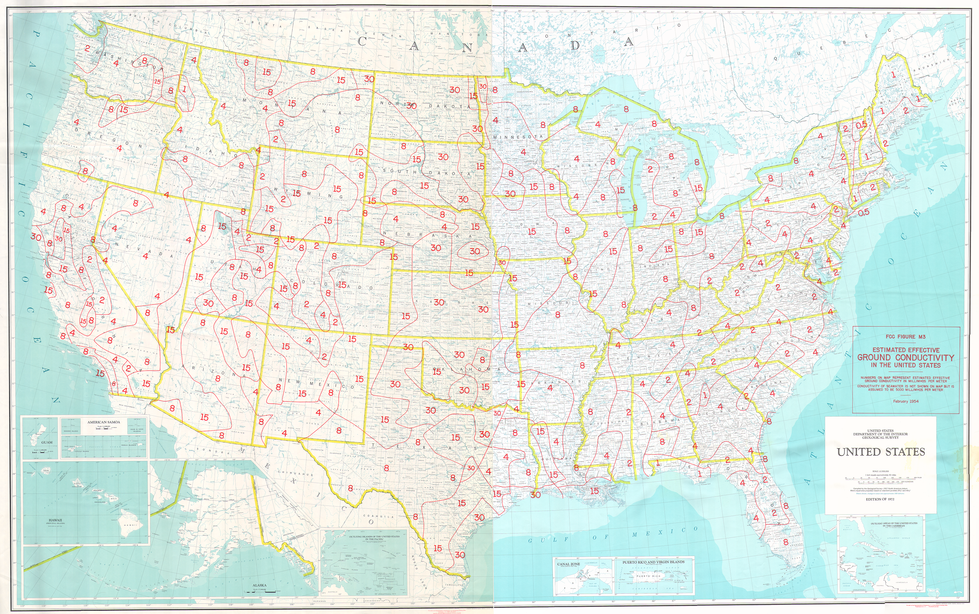
Federal Communications Commission Ground Conductivity Map,
circa 1975
From the
FCC Ground
Conductivity website:
Figure R3 of
47 CFR 73.190
of the Commission's Rules contains a map of the estimated effective ground conductivity
in the United States. This data is used to predict the propagation of AM signals
across the United States. A higher ground conductivity indicates better AM propagation
characteristics. The map shows that the ground conductivity in the U.S. ranges between
0.5 and 30 millimhos (or millisiemens) per meter. The conductivity of seawater is
5,000 millimhos per meter, resulting in the best propagation of AM signals.
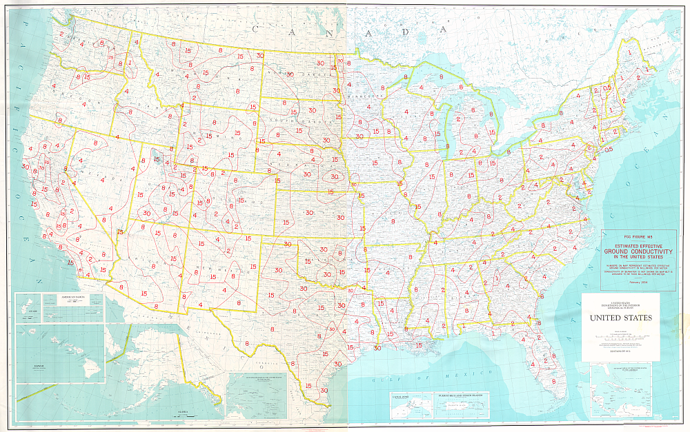
The color map here was printed for the FCC around 1975. Originally the map consisted
of two large-print sections (East and West, each approximately 45 by 43 inches.).
The sections were scanned in parts, and then the parts joined with photo-stitching
software. There may be some artifacts and minor distortion from this process, but
on the whole the map here should suffice for most purposes. The map can downloaded
in three sizes:
TIFF file,
151 MB,
PNG image,
17.6 MB, or
PNG image,
1.2 MB (pictured) .
The M3 conductivity data is also available as text files. Data for the continental
USA is located in the file
m3.seq,
which also contains updated conductivity data for the Chesapeake Bay and Puget Sound
that is not shown on the wall map. Data for Hawaii is contained in the file
m3hw.seq.
Data for the rest of Region 2 (the Western Hemisphere) is contained in the file
r2.seq.
Lastly, the M3 map segments may also be displayed in Google Earth for the continental
USA, Canada, and Mexico, via the following KML file:
Continental
USA/Canada/Mexico M3 KML.
For more information on AM and FM radio broadcasting, please visit the
Audio Division website,
and the Broadcast
Radio Links page.
Posted July 7, 2020
|


