|
|
|||||||||
| Software: RF Cascade Workbook | RF Symbols for Office | RF Symbols & Stencils for Visio | Espresso Workbook | ||||||||||
|
|||||||||||||||||||||||||||||||
   |
   |
||||||||||||||||||||||||||||||
|
Please Support RF Cafe by purchasing my ridiculously low-priced products, all of which I created. RF & Electronics Symbols for Visio RF & Electronics Symbols for Office RF & Electronics Stencils for Visio T-Shirts, Mugs, Cups, Ball Caps, Mouse Pads These Are Available for Free |
|||||||||||||||||||||||||||||||


Electrician's Mate 3 - Navy Training Courses
NAVPERS
10548

Here is the "Electrician's Mate 3 - Navy Training Courses" (NAVPERS 10548) in its entirety (or will be eventually). It should provide one of the Internet's best resources for people seeking a basic electricity course - complete with examples worked out. See copyright. See Table of Contents.
¶ U.S. GOVERNMENT PRINTING OFFICE; 1949

CHAPTER 15
SEARCHLIGHTS
NAVY TYPES
Navy searchlights are classified as to the size and source of light. The 36-inch and 24-inch searchlights use high intensity carbon arcs as the source of light, while the 12-inch searchlights use an incandescent lamp, usually a 1,000-watt lamp. The size of these searchlights is determined by the diameter of the parabolic reflector.
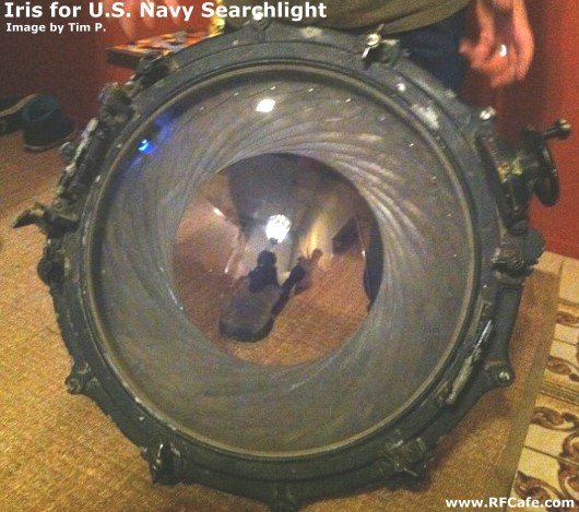
Iris Mechanism for 24" U.S. Navy Searchlight (photo by Tim P.)
"Kirt, I just found your website while looking for an explanation of the purpose of a device that a friend of my owns. It is an iris shutter for a 24" naval searchlight. Your site and description of the searchlight helped to figure out the mystery of this thing!"
"I was at a friends party new years eve and he dragged the thing out of a closet and started showing it off to those of us that were interested. It weighs about 50 lbs. I would say, it is made out of cast aluminum and the glass dome is surprisingly thin. Tempered no doubt, and it says Bausch & Lomb right on the glass. My friend bought it from an antique dealer."
USES OF SEARCHLIGHTS
The 36-inch light is used primarily for fire control. Usually they are equipped with remote control systems so they can be trained and elevated from the gun fire control director. Most are equipped with an iris shutter and may be operated either manually or by an automatic motor. The 24-inch searchlight is a general purpose light and although it may be used for fire control purposes, generally it is used for long range signaling. These searchlights are not equipped with remote control for train and elevation. The light sometimes is equipped with the remote control signal key. This lamp usually has both the iris and vane type shutter.
The 12-inch searchlight is used primarily for short range signaling. These lights are not equipped with remote control equipment, and have a manually controlled vane type shutter.
REQUIREMENTS OF A SEARCHLIGHT
A Navy searchlight must have a narrow, pencil-like light beam. The light must be non-flickering and of a 'bluish white color. It must operate properly from any position, under all weather conditions, and give trouble-free operation over a long period of time. The train and elevation characteristics of most lights are: train through 360°, elevation of 110° to 120°, and depression of 30° to 40°.
THEORY OF CARBON ARC SEARCHLIGHT
When an electric current at a moderate voltage is passed through two carbon rods, considerable heat is developed at the point of contact. Now if the carbon rods are separated a short distance a flaming arc will be drawn out.
The act of making contact between the two carbons is necessary to start the arc and is called STRIKING THE ARC. When contact first occurs, a high current flows through the carbons. The high current produces heat which vaporizes the soft center of the positive carbon. This vapor acts as a conductor for the current as the carbons are drawn apart and will keep the current flowing until the distance between the carbons becomes too great. As the distance between the carbons increases the resistance of the arc circuit increases.
The carbon vapor concentrates as a small ball in a depression in the positive carbon. This depression is called the CRATER. This ball of flaming gas in the crater is intensely luminous and is located at the focus of the reflector. The reflector thus projects the light from the arc crater into a beam of light, just as the reflector in your automobile projects the light from the lamp filament into a light beam.
HIGH INTENSITY arcs work on the same principle as low intensity types except that the current is increased and the diameter of the carbon decreased, to obtain a more brilliant and concentrated source of light.
Figure 141. - The 24-in searchlight.
SEARCHLIGHT CONSTRUCTION
The high intensity arcs require ventilation systems at all time to prevent overheating.
The arc and reflector are housed in the DRUM, which is supported on TRUNNION ARMS so that it can be tilted, to elevate or depress the beam. The BASE supports the trunnion arms so they can rotate. The drum is thus mounted so the light beam can be trained as well as elevated.
The power supply is brought up to the light through slip rings and brushes inside the base, thus permitting continual rotation in either direction. In some bases the power is brought up by flexible cables. These cables must have a long loop left in order to permit rotating the searchlight. This light can be only rotated one and a half revolutions in either direction.
Trunnion Arm. The trunnion arms support the main body of the searchlight. The drum is mounted on ball bearings located at the tops of trunnion arms, allowing for free elevation and depression of the lamp. A locking device is on the trunnion arm to secure the light in elevation and depression.
The trunnion arm rides on ball bearings mounted on the top center of the base, to allow rotation of the lamp in train. A locking device is provided on the base for securing the light in train.
Drum. The drum is the main body of the searchlight and consists of a barrel and access doors. The ventilating motor and shutter usually are mounted on or in the drum.
Vent Motor. The ventilation motor is located in a hood mounted either on the top or bottom of the barrel. The motor is connected in parallel with the arc circuit so that as soon as the lamp switch is closed the motor runs. Notice circuit of wiring in figure 142.
Figure 142. - Wiring circuit for 24-inch searchlight.
Arc Image Screen. The arc image screen is located near the top of the barrel. It contains a lens system and a ground glass screen. The screen gives the operator an indication of the condition of the arc. A marker on the ground glass screen indicates the proper position for the positive carbon. The arc image screen does not give a direct view of the arc, only an image. Figure 143 shows the correct and incorrect positioning of the carbons as viewed in the screen.

Figure 143. - Views of carbon position.
Arc Lamp. The lamp consists of the support and carbon feed mechanisms as illustrated in figure 144. The COLUMN is the upright which supports the two feed heads, and acts as a return for the negative side of the arc current. The column is hollow and allows air to flow through it to cool the positive head.

Figure 144. - Searchlight lamp mechanism.
Positive-head. The positive head is the mechanism which supports, rotates, and feeds the positive carbon. These functions are all automatic. The positive head has metal brushes to conduct the current to the carbon.
Obdurator. The obdurate is the metal shield on the positive head. It prevents the heat of the arc from reaching the gear and other exposed mechanism of the positive head. It also helps direct the light rays back to the reflector.
AUTOMATIC FUNCTIONS
The lamp has five automatic mechanisms. They are:
Forced draft ventilation.
Positive carbon feed.
Rotation of positive carbon.
Negative carbon feed.
Automatic arc striking.
FORCED DRAFT VENTILATION
The ventilation motor is usually a motor of approximately 1/12 horsepower connected across the arc circuit. As soon as the lamp switch is closed the vent motor is energized. In operation of the searchlight, the first thing to check is the ventilation.
POSITIVE CARBON FEED
The ball of vapor is the main source of light and must be kept at the focal point of the reflector. The focal point is the point where all light rays from the ball of vapor will be reflected back in parallel lines.
As the positive carbon burns back, the luminous ball of vapor will move out of the focal point. Therefore, some means must be made to keep the luminous ball of vapor at the focal point. This is accomplished by feeding the positive carbon forward as fast as it burns away.
The positive feed system contains a thermostatic switch, a solenoid, a lever and gear system. The power to rotate the positive head is furnished by the feed motor. The feed motor is connected across the arc circuit and runs when the lamp switch is closed.
The thermostatic switch in figure 145 is made of two metal strips welded together. When heated, one strip expands faster than the other and closes the circuit to the positive mechanism. When the positive carbon is in the proper position the heat rays from the arc vapor do not fall on the bimetallic strip. The switch will then be open and cuts off the feed current. As the carbon burns back the heat rays once more strike the bi-metallic strip, closing the feed circuit and feeding the positive carbon forward.
Figure 145. - Thermostatic switch, positive feed mechanism.
ROTATION POSITIVE HEAD
The positive carbon must be rotated all the time in order to keep the crater that holds the ball of luminous gas symmetrical. The feed motor is connected across the arc. circuit so that the motor runs all the time the switch is closed. The positive head mechanism is geared directly to the feed motor. The positive head rotates as long as the light is in operation.
PEEP SIGHT
The peep sight is a small circular opening with a colored glass window to give the operator a direct view of the arc.
REFLECTORS
The reflector is a parabolic mirror which collects the light rays and reflects them in a parallel beam. Two types are in use, glass and metallic.
Glass Reflector. The glass reflectors are made of optical glass with the reflecting surface coated with silver. It is efficient but has two disadvantages: first, breakage due to intense heat in drum and due to shock; and secondly, the. silver peels. This reflector should be cleaned only with alcohol and precipitated chalk.
Several metals such as chromium steel, coated aluminum and other alloys are used in manufacturing the METALLIC REFLECTOR. They are not subject to breakage or peeling. This reflector may be cleaned with bright work polish or any polish not containing an abrasive. In cleaning NEVER USE A CIRCULAR MOTION - always WIPE FROM the CENTER OUT.
SHUTTERS
Shutters are provided so the light beam may be secured without securing the lamp. They are mounted in the front of the barrel and are of two types - the VANE SHUTTER and IRIS SHUTTER.
The IRIS SHUTTER is light proof. It can be operated manually or by a control motor. This shutter is too slow to be used as a signal shutter. It should be cleaned and lubricated according to manufacturer's instructions.
The VANE type SHUTTER is used for signaling and is primarily a speed shutter. May be operated by manual control or by an automatic key. This shutter is not fully light proof.
RHEOSTAT
The rheostat has a low resistance and high current carrying capacity. One of its most important functions is to prevent a direct short circuit when the arc is first struck. It should be set for the proper operating current of the searchlight, and after its initial setting, should not require adjustment unless a change in the operating current is made.
CURRENT CONTROL NEGATIVE FEED
Feeding of the positive carbon is automatically controlled so that the crater is always at the focus of the reflector. The negative carbon feed is also automatically controlled, to keep the arc length constant. Two types of automatic negative feed are used - CURRENT and VOLTAGE types.
A CURRENT CONTROL negative feed system may be identified by coil wound with heavy strip copper and connected in series with the arc circuit. The current control feed system depends upon a varying current through the arc to actuate the system. The equipment consists of a current coil and plunger which regulate a motor drive for feeding the negative electrode. One end of a pivot arm is attached to the plunger and the other end of the arm is attached to a spring. The current coil is in series in the negative side of the arc circuit.
When the lamp switch is first closed, a very small current flows. This allows the spring to overcome the pull of the current coil, and pull the lever arm down so as to engage the high speed forward feed. The negative carbon is fed forward until it makes contact with the positive carbon. When the carbons strike, there is a high rush of current. This high current cause the current coil to overcome the pull of the spring and engage the reverse high speed feed, thus pulling the negative carbon back and drawing out the arc. When the pull of the current coil and spring tension are in balance the negative carbon will cease to feed.
Any change in arc length after the arc is struck will be taken care of by the low speed gears. The action of the current coil is the same as in the high speed feed except the feed lever engages the low rather than the high speed gears.
Figure 146. - Positive carbon feed drive mechanism.
If the negative carbon were fed too far forward the arc current would increase, causing the coil pull to overcome the pull of the spring tension and engaging the slow speed reverse gears to feed the negative carbon back until the arm balances.
In a current control negative feed system INCREASING the SPRING TENSION will DECREASE the ARC LENGTH and decrease of the spring tension will increase the arc length.
VOLTAGE CONTROL NEGATIVE FEED
In the VOLTAGE CONTROL negative feed system, the voltage drop across the arc circuit operates the system. It consists of a voltage regulator coil, plunger, pivoted arm with a spring attached to the opposite end of the pivot arm. As soon as the lamp switch is closed there is a high voltage drop across the arc circuit allowing the coil pull to overcome the spring tension and feed the negative carbon forward. Upon striking the arc there is a high rush of current, causing a low voltage drop across the arc circuit, pulling the arm down and engaging the high speed reverse feed. The negative carbon feeds back until the pull of the coil and the spring tension just balance. Any further change due to carbon burning back will be taken care of by the slow speed units.
The voltage control system can be identified by looking for a regulator coil. Voltage control will have many turns of fine wire connected in parallel with the arc circuit. On a voltage control searchlight if the SPRING TENSION is INCREASED the ARC LENGTH INCREASES; if spring TENSION is DECREASED the ARC LENGTH DECREASES.
MANUAL CONTROL
Manual control gear is installed on all searchlights so the searchlight may be operated in case of failure of the automatic system. All of the automatic functions except ventilation can be operated manually. The manual control gear has two small cranks located on the back of the lamp box; one controls rotation of the positive head, the second controls the feed of the negative carbon. A push button controls the feed of the positive carbon.
ADJUSTMENTS
The angle of the negative carbon in relation to the positive carbon must be correct. If the angle is too great or too small the crater of the positive carbon will burn off on one side and allow the ball of vapor to escape. See the lamp instructions book for the correct setting and method of adjustment.

Figure 147. - Carbon feed heads for Sperry 36-inch searchlight.
ADJUSTMENT OF CARBON BRUSH PRESSURE
A proper contact between the heads and the carbons is necessary. If brush pressure is too great the carbons will stick and not feed properly and if too loose will not give good contact. When correctly set it should take a pull of 8 to 10 ounces to slip the carbons out of the head with the feed rollers raised.
ADJUSTMENT OF POSITIVE CARBON PROJECTION
The positive carbon must project a distance of 9/16-inch for for the 24-inch light, 15/16-inch for 36-inch light, in front of the positive head. This prevents the noses from burning and assures proper focus. To make this adjustment allow the searchlight to operate several minutes. Then secure the light and measure the distance from the positive carbon tip and the positive nose. If this distance is incorrect, the procedure for adjusting follows.
If the positive carbon is not projecting out far enough shift the lens, figure 145, in the direction you wish the carbon to feed. Shift lens only about 1/16 inch at a time. After the lens has been shifted the lamp must be operated several minutes, and rechecked. This must be repeated until the projection is correct.
ADJUSTMENT OF ARC LENGTH
The first step in adjusting the arc length on a current control searchlight is to determine the proper operating amperage. You can find this in the instruction book on the light. If the switchboard does not have an ammeter in the arc circuit, connect in a portable ammeter. If the arc current is too high, decrease the spring tension. This will lengthen the arc and decrease the arc current. If the arc current is too low increase the spring tension. This will decrease the arc length and increase the arc current.
For adjusting a voltage controlled searchlight feed determine the proper arc voltage. If the switchboard does not have a voltmeter for the searchlight, connect a voltmeter across the arc circuit. If the arc voltage is too high, increase the spring tension. If the arc voltage is too low, decrease the spring tension. Always CONSULT the INSTRUCTION BOOK WHEN MAKING ADJUSTMENTS.
FOCUS
After the preceding adjustments have been made, the lamp should be focused. A focus screw on the back of the lamp box moves the entire lamp mechanism toward or away from the reflector. Operate the light for several minutes then secure and measure the positive carbon tip projection. Then measure the distance from the tip of positive carbon to the center of the reflector. This distance should correspond with the focal length given on the reflector.
CARBONS
In 24-inch searchlights a pair of carbons will last approximately 105 minutes, in a 36-inch light at 150 amperes, about 90 minutes and at 190 amperes, about 45 minutes. Spare carbons should be stored in original containers in a dry clean space.
PRECAUTIONS FOR RECARBONING
Always MAKE SURE LAMP SWITCH IS OFF WHEN RENEWING CARBONS.
IF LAMP IS HOT USE GLOVES AND PLIERS to renew carbons.
CHECK CARBON to make sure it is not cracked or warped.
Always START an operation WITH COMPLETE NEW SET OF CARBONS. Never use a set of stubs. After renewing carbons operate the light for about three minutes to form the crater in the positive carbon.
REAMING POSITIVE AND NEGATIVE NOSES
The positive and negative noses should be reamed when needed to remove carbon and other obstruction to insure freedom of carbon to feed. Reamers are furnished as spare parts. The following precautions should be followed: In reaming always hold reamer straight, make sure feed rollers and brushes are lifted, and IF REAMING WHILE LAMP IS HOT. NEVER ALLOW REAMER TO STOP moving UNTIL NOSE IS COMPLETELY REAMED. This is to prevent reamer from becoming stuck as the metal cools.
CLEANING REFLECTORS AND DOME
The reflector and dome glass should be cleaned each time after the light is used. NEVER USE POLISH CONTAINING ABRASIVES.
Use mixture of denatured alcohol and precipitated chalk to clean reflector; the mixture should consist of three ounces of chalk to 1/2 pint of alcohol. This paste may be removed with cheese cloth. NEVER USE A ROTARY MOTION. Always POLISH FROM THE CENTER OUT. Use a cloth to remove residue of carbons from the burning interior of drum. This residue is a white powdery ash. A small paint brush or painter's duster serves as well to remove carbon particles from the thermostat lens and top of lamp.
LUBRICATION
The manufacturers instruction book gives information for lubricating base, trunnion arms, and lamp. Grease or oil should never be used on the heads. To lubricate heads use a mixture of flake graphite and kerosene at least once a week. The iris shutter should be given a light coat of graphite and kerosene once a month.
PERIODIC TESTS, INSPECTIONS AND CLEANING
AFTER EACH PAIR OF CARBONS -
Wipe reflector, glass door and thermostat lens.
AFTER EXTENDED RUN -
Clean interior of drum, thermostat window and lens and the lamp mechanism.
As soon as the reflector has cooled, clean the reflector and front door glass.
AFTER FIRING -
After each period of firing of the ship's batteries, inspect all searchlights.
DAILY -
Test local mechanical gear for training and elevating light, then the remote control or
distant mechanical control gear.
Check remote electrical control gear on searchlight.
Operate each lamp long enough to dry out drum and test functioning of lamp mechanism.
Check ready light for full pair of carbons.
At sea and during damp weather, energize remote control electrical equipment to
insure dryness.
WEEKLY -
Clean reflector and front door glass.
Clean interior of drum, thermostat, window and lens, and lamp mechanism.
Check nose caps for insulation to heads and to ground.
Examine exposed gears and bearings for lubrication and for freedom from dirt, sand
and grit.
MONTHLY -
Remove, examine and clean the metal contact blocks which conduct current to the carbons.
Clean carbon feed rollers.
AFTER 50 HOURS OF OPERATION OR QUARTERLY -
After 50 hours of operation and not less than once each quarter, remove the lamp
from the drum, overhaul, reinstall and reset the lamp.
YEARLY -
Inspect, lubricate, and repair equipment in the base.
Chapter 15 Quiz

Copyright: 1996 - 2026 |
About RF Cafe RF Cafe began life in 1996 as "RF Tools" in an AOL screen name web space totaling 2 MB. Its primary purpose was to provide me with ready access to commonly needed formulas and reference material while performing my work as an RF system and circuit design engineer. The World Wide Web (Internet) was largely an unknown entity at the time and bandwidth was a scarce commodity. Dial-up modems blazed along at 14.4 kbps while tying up your telephone line, and a lady's voice announced "You've Got Mail" when a new message arrived... |
Copyright 1996 - 2026 All trademarks, copyrights, patents, and other rights of ownership to images
and text used on the RF Cafe website are hereby acknowledge My Hobby Website: My Daughter's Website: |
