|
|||||||||||||
 |
|||||||||||||
Chevrolet Remote Keyless Entry (RKE) Fob Teardown |
|||||||||||||
|
The image to the left is how it should have looked, with the battery holder firmly soldered in place on the PCB. The main electrical contact is the large tab at the top center, but there are also small fingers protruding from the bottom on both sides of the fingers that solder into holes in the PCB. Those two tabs connect to the same point in the circuit electrically, so for this device to fail, all three solder joints needed to fail. They did. To the right is what the assembly (or should I say disassembly) looked like. A quick check with the DMM showed that the CR-2032 battery still had a charge of 3.20 volts after all this time - impressive.
The cause of the poor soldering job is most likely the large thermal inertia of the metal battery holder prevented it from attaining proper solder wetting temperature during the reflow process, so a cold solder joint resulted. My re-soldering job was effortless since the tinning on the metal was quite sufficient to facilitate wetting. Out of curiosity, I popped open Melanie's RKE fob and inspected the solder joints on hers. Sure enough, one of the through-hole fingers had a cracked solder joint. I repaired that, too. If I had taken my fob to the Chevy dealer, you can bet he would have wanted to charge me $100 for a new one when clearly it was a manufacturing defect. Alright, as long as the beast was apart, I felt compelled to take an inventory of the components used. As you can see, the parts count is very low. The first thing I do is look up the FCC ID code that by law is printed on all wireless devices in the USA. Many times there will be very useful photos and data available for public viewing that was submitted by the laboratories that performed the qualification testing. Not so on this device (FCC ID: KOBGT04A), which is registered to Lear Corporation, in Southfield, Michigan, near Motor City, aka, Detroit.
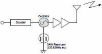
The UHF oscillator circuit looks to be a single transistor that is interfaced directly to the antenna. Its frequency determining device is likely the oval lidded package which is probably either a ceramic or SAW resonator (it bears a muRata logo and the package marking of 31kV). The oscillator circuit is gated on and off by the DATA output of the HCS device.
The printed antenna is clearly visible along the top perimeter of the PCB.
|
|||||||||||||
 |
|||||||||||||
|
|||||||||||||


 A visual inspection (click on
image above for closer look) shows that there is an 8-pin SOIC that is the RFID IC brains.
Its package marking is 0218-002/PR0619/3PS, and is made by
A visual inspection (click on
image above for closer look) shows that there is an 8-pin SOIC that is the RFID IC brains.
Its package marking is 0218-002/PR0619/3PS, and is made by

 So in all, the
discrete component parts lists is comprised of 1 integrated circuit, 1 resonator, 3 resistors,
5 capacitors, 2 diodes, and 1 three-pin transistor. Add in a 2-layer PCB, a plastic housing,
rubber switch pad, and a battery, and that is the totality of it.
So in all, the
discrete component parts lists is comprised of 1 integrated circuit, 1 resonator, 3 resistors,
5 capacitors, 2 diodes, and 1 three-pin transistor. Add in a 2-layer PCB, a plastic housing,
rubber switch pad, and a battery, and that is the totality of it.


|
||||||||||||||||||||||||||||||||||||