|
|||||||||||||
 |
|||||||||||||
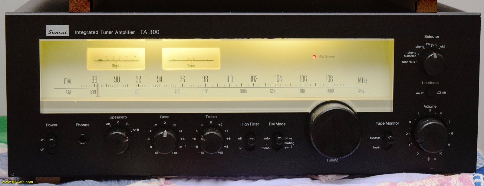
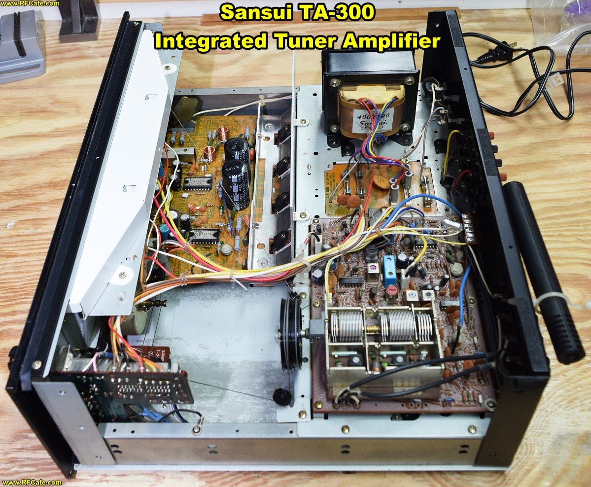
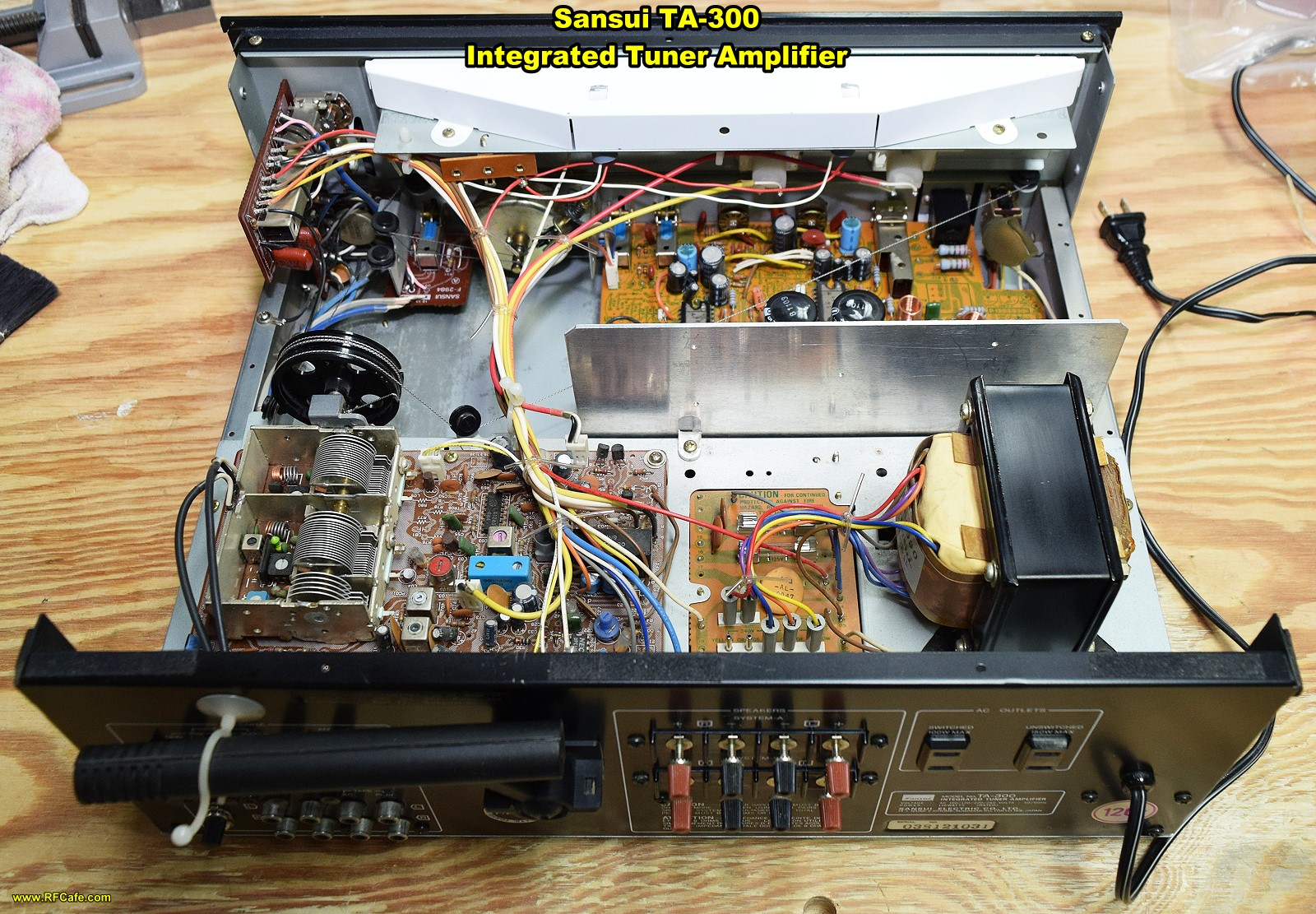
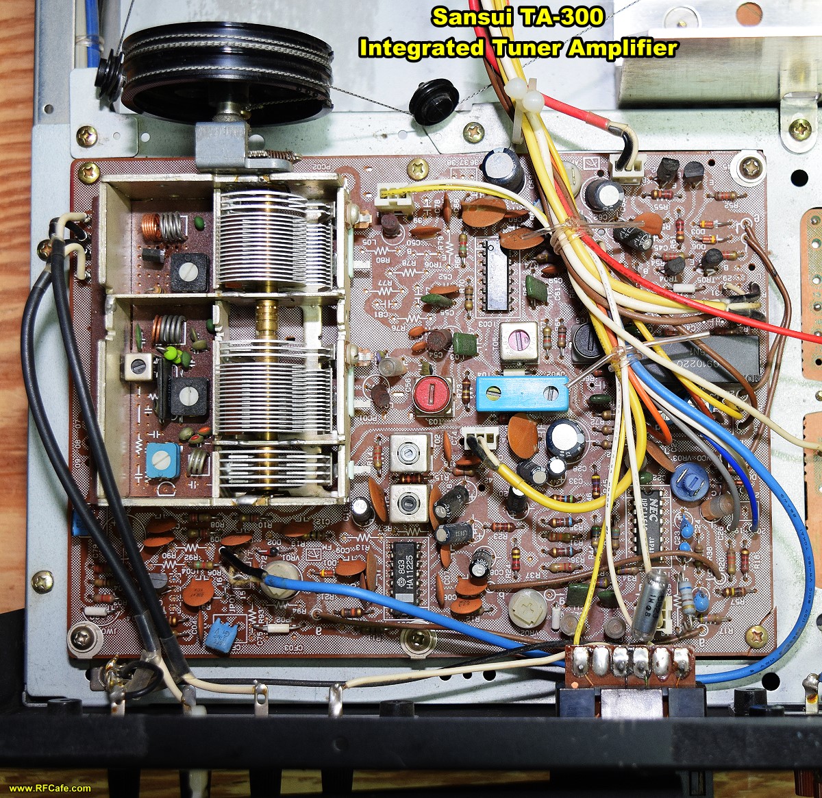
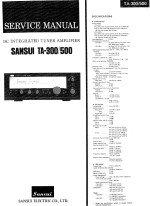
Sansui TA-300 Integrated Tuner Amplifier
|
|||||||||||||
|
1 | 2 | 3 | 4 | 5 | 6 | 7 | 8 | 9 | 10 | 11 | 12 | 13 | 14 | 15 | 16 | 17 | 18 | 19 | 20 | 21 | 22 | 23 | 24 | 25 | 26 | 27 | 28 | 29 | 30 | 31 | 32 | 33 | 34 | 35 | 36 | 37
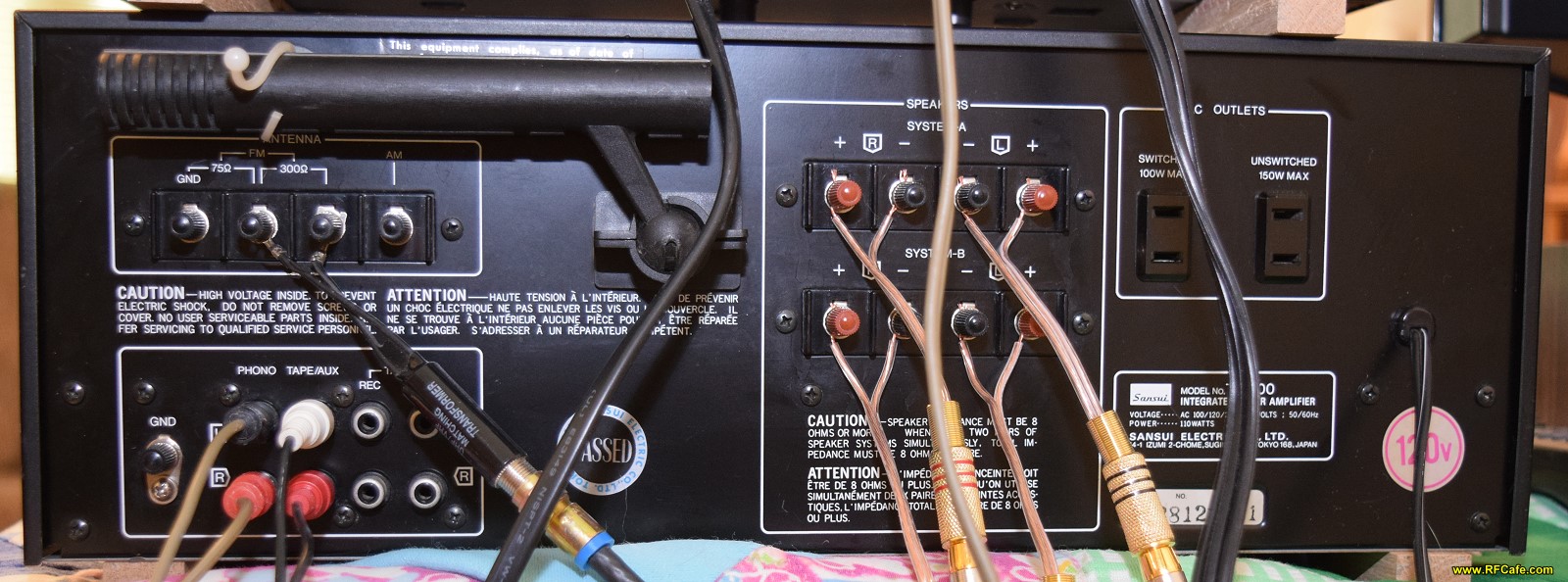
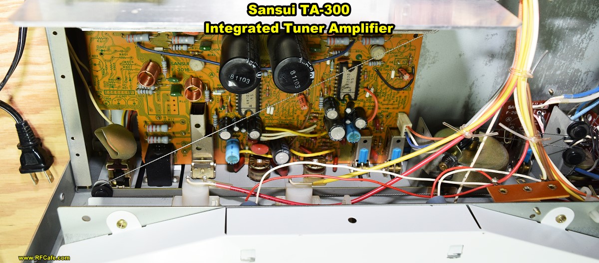
Sansui TA-300 Integrated Tuner Amplifier rear panel.
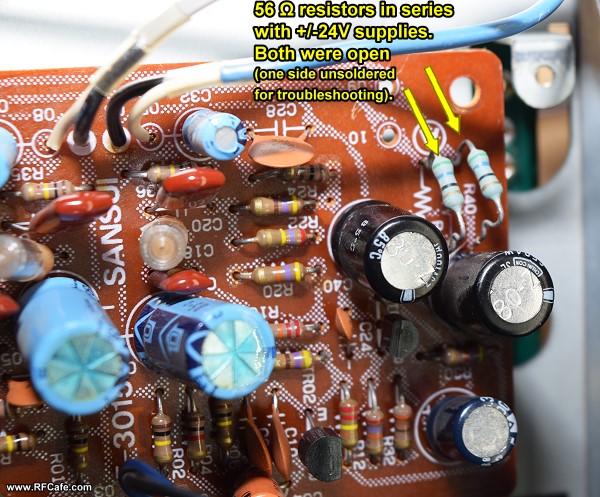
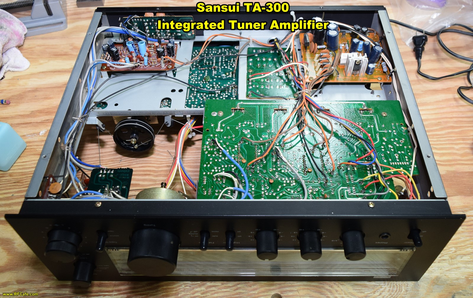
±24 V power supply series resistors measured open.
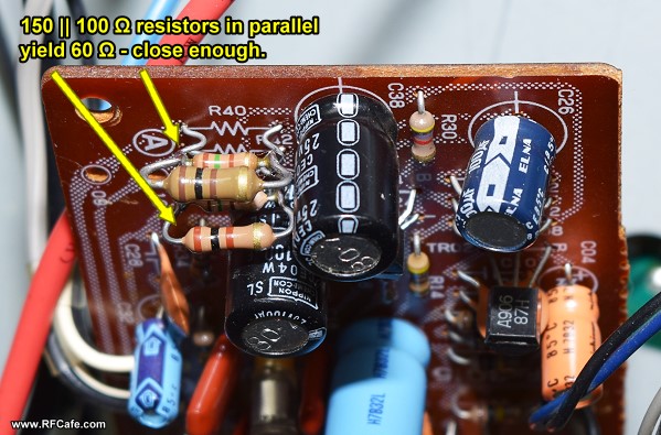
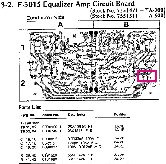
56 Ω, ¼ W series resistors (R40 and R42). I didn't have any 56 Ω resistors, so I paralleled a 150 Ω and a 100 Ω.
Upon receipt (he did an excellent packing job), I removed the cover and blew out the chassis with compressed air (very little dust) and wiped down the inside and outside of the chassis. It was very clean all over with only minor visible wear. Next, I set the chassis up on my workbench and patched in some test speakers and a 1 kHz sinewave for use with the various external inputs. The "A" and "B" speaker outputs checked out for both Left and Right channels using the FM and AM radio tuner. Then the test signal was fed into the Aux and Tape jacks to verify operation. Last, saving the known problem for last (good news first), I moved on to the Phono input and discovered that the Left channel functioned properly, but the Right channel was dead. At that time, I had not yet found a free, downloadable Sansui TA-300 User's Manual, so I began probing with the oscilloscope to see how far into the circuit the external signal got. It went to the base of the first transistor, with no signal on the collector or emitter. Since the Left channel was working, I compared the signals to it and found that the DC power rails were way off. Accordingly, I started checking the DC power input. To my surprise, I discovered that both of the 56 Ω, ¼ W series resistors (R40 and R42*) measured as open circuits. Neither of them appeared to be overheated, nor a burnt odor, nor were brittle or broke when removed, at least one of which symptoms typically are present when a resistor "blows." The capacitors and other components in the region measured good, as did the transistors. I took a chance and soldered in replacement resistors and fired it up. Everything worked perfectly (and is still working a day later). I am completely perplexed as to how those two resistors could have gone bad, but I'm equally thrilled that replacing them did the job! * The schematic for the F-3015 Equalizer Amp Circuit Board shows a different value as used for the 50 W (TA-500) model, but a note on the page affirms the 56 Ω values.
|
|||||||||||||
 |
|||||||||||||
|
|||||||||||||
 "
"


|
||||||||||||||||||||||||||||||||||||


