As radio frequencies moved
up into the UHF realm of
30 MHz (through 3 GHz), designers noticed that the old methods and equations
for winding inductors (aka coils and chokes) no longer performed as predicted. The
culprit was stray capacitance created by the wire itself and the insulation between
windings. To some extent, the length of leads running from the inductor windings
to connection points (terminal strips and lugs at first and then later printed circuit
boards) generated enough extra inductance to add noticeably to total inductance.
New methods were developed to help mitigate the effects of these stray (aka parasitic)
reactances. Much new knowledge in this area was gained through the war efforts with
many radar and radio designs coming online during the time.
R.F. Chokes at U.H.F.

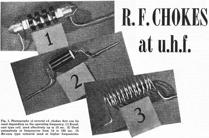
Fig. 1. Photographs of several r.f. chokes that can be used
depending on the operating frequency. (1) Broadcast type coil, used effectively
up to 10 mc. (2) Used extensively at frequencies from 10 to 180 mc. (3) Air-core
type solenoid used at higher frequencies.
By W. J. Stolze
With the assignment of many services to higher frequencies, the electrical
characteristics of component parts must be carefully analyzed.
With the advent of FM and television, the radio serviceman, who for the past
twenty-odd years has been ably repairing amplitude-modulated (AM) broadcast receivers,
must now familiarize himself with good design and construction technique in the
recently assigned high-frequency bands. A thorough working knowledge of the various
problems which become apparent at high frequencies will not only increase the pleasure
that a radio amateur can extract from his hobby, but will also be very profitable,
for in the immediate future the majority of sets brought into the small service
station for repair will be high frequency FM and television receivers. With an eye
to the future, this article will discuss the design and application of radio frequency
chokes in the new v.h.f. bands.
The proper selection of a correct r.f. choke, even though often ignored, misunderstood,
and underemphasized, is an important factor in obtaining the best possible performance
from a well-designed unit of equipment. The most important circuit application of
the choke is in series with the B+ plate voltage supply of high-frequency oscillators.
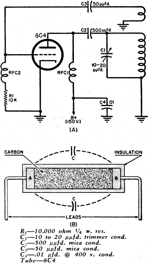
In Fig. 3A a typical FM local oscillator is shown. The choke, RFC1
is inserted in series between the plate of the tube and the B+ voltage supply. At
the frequencies used, if this choke were not present a portion of the available
power output of the oscillator would be dissipated in the plate power supply. This
is a serious situation when maximum power output is required. The condition can
be equated as follows:
Power Output = Power Available - Power Dissipated
A typical circuit uses the 6C4 and is capable of delivering about four watts
maximum output. With improper choking, as much as two watts may be lost in the power
pack, leaving only two watts, or 50% maximum power, available as useful output.
This condition also exists and is even more serious in high power transmitter oscillators.

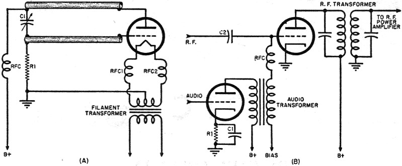
Fig. 2. (A) In higher frequency applications r.f. chokes
must be employed in the filament circuits to prevent oscillations. Proper method
of grounding is shown. (B) Circuit for grid bias modulation. R.f. choke prevents
r.f. from entering modulation transformer.
Fig. 3A also includes a choke, RFC2, in the grid-leak circuit.
Most setups require this choke, as its omission may be cause for the oscillator
to cease operation. A diagram of the typical grid-leak resistor is shown in Fig. 3B.
A carbon rod forms the resistive element, which is flanked on each side by small
round metal plates, A and B from which the terminal leads are brought out. Bakelite
or ceramic covering is added as insulation. A stray capacity exists between these
plates, A and B, which at high frequencies may be of such magnitude as to bypass
enough of the signal from the grid to ground to prevent oscillation.
In the 200 to 600 megacycles per second section of the frequency spectrum, transmission
lines make then appearance as tuned circuits for power oscillators. At these frequencies
another problem appears. High percentages of the power may run down the leads of
the filament and be lost in the filament transformer. Correction of this condition
is essential since the same problem exists as did with improper plate supply chokes.
Fig. 2A illustrates the application of r.f. chokes in the filament leads, and
one of a number of correct methods of grounding. As the frequency approaches 600
megacycles, and above, however, it becomes convenient to feed the heaters through
tuned transmission lines, which then act as r.f. chokes.
Confining r.f. to particular sections of a circuit and eliminating it in other
sections is another use to which r.f. chokes are put in modulating apparatus. In
Fig. 2B a circuit for grid-bias modulation is shown. Here the r.f.c. prevents
the r.f. from flowing in the modulating transformer.
Of course there are many other applications of r.f. chokes, but those which are
most important and those which the average radio serviceman or radio ham are most
likely to encounter have been included in the above discussion.

Fig. 3. (A) Diagram of FM local oscillator, shows most common
application of r.f. chokes. (B) Common grid-leak type resistor.
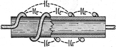
An important characteristic of chokes which is very often forgotten or ignored
is that the choke must be a very high impedance at the operating frequency and not
just a high inductance. If this condition is not fulfilled a serious detuning of
the tank circuit may result. This statement at first appears paradoxical, but can
be easily explained with reference to Fig. 5. It shows a number of coils of
wire wrapped around a Bakelite form. Small capacities (distributed) exist between
each pair of turns on the coil. Classically a condenser consists of two flat plates
of a conducting material separated by an insulating dielectric. In this case the
two turns of wire form the plates and the interspace air forms the insulator. A
condition of this nature exists with every coil. Even though the distributed capacity
is small, it is impossible to make it zero; therefore, the optimum in choke design
appears when the inductance of the coil resonates with its own distributed capacity
at the operating frequency.
In actual practice, self-resonance is almost impossible to obtain exactly, because
stray capacities which arise in the circuit wiring almost always detune the choke
somewhat, but a condition as close as possible to the goal will pay the highest
dividends. Too many turns will result in a very large stray capacity and, at a frequency
any appreciable amount above resonance, the choke will appear to be a shunt condenser.
A Boonton Q Meter is an excellent instrument on which to measure resonant frequencies
of chokes, but since such an instrument is expensive and therefore not available
to the average amateur, several graphs are included to aid in the design of high-frequency
chokes.
Other characteristics of chokes that are important are the current carrying capacity
of the wire, which must be high enough for the desired application, and the resistance
of the choke, which must be low enough not to cause an appreciable voltage drop.
Remembering this construction hint will save many hours of time search-ing for
the cause of trouble in new FM sets.
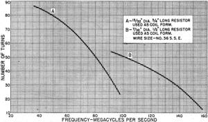
Fig. 4. Design chart shows approximate number of turns vs.
frequency for r.f. chokes.
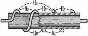
Fig. 5. Distributed capacities that will have effect on
the operation of choke.
Now for a sample design of a choke.
Sketches of several chokes used at various frequencies are pictured in Fig. 1.
Type 1 is used mainly in the broadcast band and up to approximately 10 megacycles.
Construction of this of choke is difficult, as it necessitates the application of
a universal coil-winding machine and is therefore out of the scope of most amateurs
and radio builders. Choke number 2 is useful for frequencies from about 10 megacycles
up to about 180 megacycles. Above this frequency, air-cored solenoids, type 3, are
used.
Ceramic insulated resistors, with values ranging from 1 megohm up, provide the
best form on which to wind a home-constructed choke. This material has about the
least losses of any readily available. Isolantite is used commercially, but this
is essentially the same thing. The 1-megohm resistance is high enough so that its
effect upon circuit Q's is negligible. Another advantage of a resistor is that its
terminal leads are excellent in facilitating the use of short connections.
All choke connections at high frequencies should be as short as it is possible
to make them. This point cannot be overemphasized, as long leads add dangerous amounts
of inductance and capacitance at the frequencies used in the new FM band.
An excellent illustration of this condition can be shown by the following analogy:
A lead 1" long at 100 megacycles has the same inductive reactance that a lead 8'4"
long has at standard broadcast frequencies. How absurd it is to think of hanging
an 8-foot connection lead in an AM receiver.
Let's say a choke is desired for the plate circuit of a local oscillator of an
FM set (Fig. 3A). An excellent high-frequency oscillator tube is the Radiotron
6C4 miniature triode. The first factor that comes into consideration is the current
that the plate will draw at maximum output. In the design chart shown in Fig. 4,
values are given for chokes wound on two different sized cores, using No. 36 single
silk enamel wire. The No. 36 wire can carry 25 milliamperes. One watt, 13/32" -diameter,
and one-quarter watt, 7/32" diameter, ceramic insulated resistors are the two sizes
of forms covered by the chart. Plate current in a small receiving tube is generally
not over 25 milliamperes, so the No. 36 wire will suffice for this circuit.
A point in the middle of the band is the optimum frequency to choose for the
design. The present band is 88 to 108 megacycles; therefore, 98 mega-cycles will
be the design frequency for our choke. On the chart, using a 7/32" form, it can
be seen that 51 turns will fulfill the specifications.
To begin construction, sandpaper the marking paint off the body of the resistor
and solder one end of the wire to a terminal lead. After winding the required number
of turns, cut the wire to size and fasten it to the other lead with solder, being
careful to keep the coil tight, neatly wound, and closely spaced. If the design
chart has been followed with any degree of accuracy, a choke has been made that
is applicable in either the plate or the grid leak circuit of the oscillator, RFC,
and RFC, of Fig. 3. Two identical coils should be wound.
All the design and construction de-tails presented in this article are important.
Following them will not insure success, of course, but it will certainly be a tremendous
aid. The following are a number of general construction rules for u.h.f. work:
1. Keep all leads as short as possible;
2. Construct the chassis, circuit. and other parts sturdily;
3. Do not use inferior components. Even though u.h.f. is a new field, the amateur
or radio serviceman should not hesitate for a moment to enter it, for it is an unexplored
wilderness with great opportunities for fascinating home research.