|
June 1952 Radio-Electronics
 [Table of Contents] [Table of Contents]
Wax nostalgic about and learn from the history of early electronics.
See articles from Radio-Electronics,
published 1930-1988. All copyrights hereby acknowledged.
|
During the early days of remote
(radio) controlled models - airplanes, boats, and cars - the only way to legally
operate an R/C was by possessing an amateur radio operator's license. At some point
in time around when this article appeared in a 1952 issue of Radio-Electronics
magazine, part of the 27 MHz band allocated to Citizens' Band radio was opened
to low power radio control. Even then, a radio operator's permit from the FCC was
required for use, which in 1974 I paid to obtain (too bad I don't still have it).
My first R/C system, purchased used from a guy down the road who was heavily into
radio controlled models of all sorts, was on 27.195 MHz. It was a
3-channel Digitron DP-3 system manufactured by OS Digital (in Japan), although
there was only analog circuits in the transmitter, receiver, and servos. The FCC
designated five frequencies for R/C in the
72 MHz band in 1965,
then a total of about 60 channels by the late 1980s. In 2004, the first spread spectrum
R/C system was introduced, operating in the 2.4 GHz ISM band. In 1952, there
was not much in the way of proportional control of movable surfaces - rudder, elevator,
aileron, engine throttle, etc. Motorized servos were just beginning to come to market,
but they were basically neutral, full throw left, or full throw right. It was an
electromechanical substitute for the
rubber band-powered escapements shown here. The
Raytheon RK-61 subminiature
vacuum tube triode was designed especially for remote control receivers, and uses
only 1.5 V for the filament and 48 V on the plate.
Model Plane Control ... with 27-mc Signals
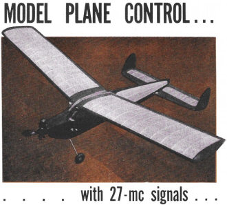 A fascinating hobby - combining the techniques
of electronics and flying - now open to non-amateurs too, with the assignment of
an exclusive Citizens'-Band spot frequency. Simple equipment gets you started. A fascinating hobby - combining the techniques
of electronics and flying - now open to non-amateurs too, with the assignment of
an exclusive Citizens'-Band spot frequency. Simple equipment gets you started.
By E. J. Brown
Military use of guided missiles and radio-controlled miniature planes for targets
and test purposes has become a part of everyday news. The use of radio control has
spread to amateurs who build and fly small gas-engined planes as a hobby. The development
of miniature components and compact hearing-aid batteries have reduced the size
of radio-controlled model planes to half that of prewar types.
The opening of the Citizens band and the marketing (by the Vernon McNabb Co.)
of a complete Citizens band control unit, including a transmitter, receiver, and
escapement control, has greatly expanded the number of radio-controlled-model builders.
One of the most valuable aids to radio control of plane. models is the Raytheon
RK-61 tube. This tube, a gas thyratron triode, requires so little operating current
that it is possible to reduce the weight of the airborne radio equipment to only
7 1/2 ounces. The RK-61 was in short supply for a while, but is now available again.
A British tube, the XFG-1, also may be used without any circuit changes.
This article describes a complete model-control system which can be easily constructed
in the home. It is intended for use in the amateur bands above 26.960 mc., and on
the new Citizens band radio control frequency of 27.255 mc. While much radio control
work is also being done on the 460-470-mc Citizens band, the RK-61 thyratron is
not considered suitable for use at frequencies above 100 mc. (Editor's note: No
attempt should be made to use radio control for any purpose until the necessary
licensing requirements have been met. Consult the FCC for latest regulations.)
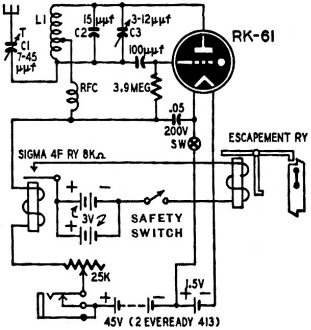
Fig. 1 - Schematic of the receiver. An incoming signal closes
the relay contacts.

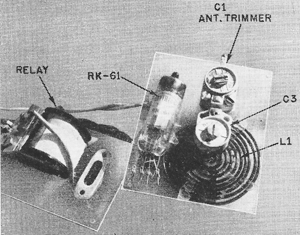
Fig. 2 - Close-up view of the receiver tuning assembly, showing
the special spirally-wound tuning inductor. The underside of the control relay for
the escapement mechanism appears at the left.
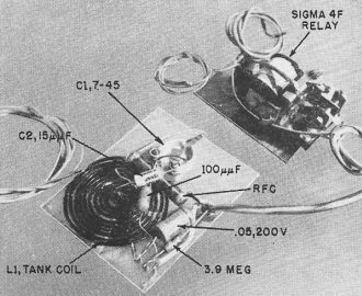
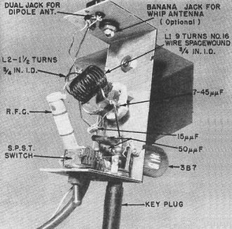
Fig. 3 - The opposite side of the receiver mounting plate, showing
the placement of related components and the connecting cable to the control relay
unit.
The 27-mc transmitter assembly.
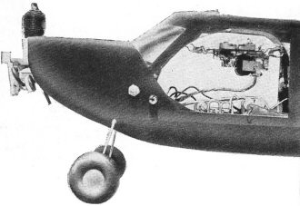
A typical receiver installation in the cockpit of a flying plane
model.
The schematic of the superregenerative receiver which is mounted in the plane
or other controlled unit is shown in Fig. 1. A spiral-wound inductor L1 is used
to reduce space requirements. L1, consisting of 9 1/2 turns of No. 16 enameled wire
with a tap at about 3 1/2 turns from the inside, can be seen in Figs. 2 and 3. The
relay and the escapement-type control unit (Fig. 4), which moves the rudder, are
separate, and may be mounted in any convenient location in the model.
The receiver is constructed on a base of polystyrene as shown in the photos.
Do not solder the tube wires directly to components, as it may damage the tube and
would prevent quick removal. All parts are standard except the r.f. choke, which
is made from a burned-out tubular glass fuse, close-wound with a 1-inch long, single
layer of No. 32 enameled wire. The three-wire cable connects the receiver to the
relay and the batteries.
If dimensions vary from those shown it may be necessary to change the value of
the fixed band-spread capacitor C2 to keep the receiver in the band. The L-C ratio
of the tank is not critical, but if trouble is experienced try varying the number
of turns on the coil and try changing the point of the choke connection to control
regeneration.
A 25,000-ohm potentiometer is used to control plate current. Filament current
is supplied by two penlite cells wired in parallel. A switch in the A plus-B minus
lead turns the receiver on or off.
A closed-circuit jack is used in the B plus lead for plugging in a 0-5-ma d.c.
meter to tune the receiver. The no-signal plate current should read between 1.3
and 1.5 ma, dropping to 0.1 to 0.3 when a signal is received. The receiver antenna
should be a piece of stranded wire about 60 inches long. Lengths as short as 18
inches will work at short ranges. The antenna-tuning capacitor, C1, will compensate
for incorrect lengths.

Fig. 4 - The escapement mechanism. The parts are identified and
described below.
1. Bulkhead.
2. Rubber loop, 1/8-inch flat rubber.
3. Crank-pin hook, 1/16-inch music wire.
4. Frame, 0.025-inch hard brass sheet.
5. Bearing, model airplane type.
6. Control arm, 1/8-inch brass rod.
7. Bushing, brass tubing.
8. Rudder.
9. Yoke shaft, 1/16-inch music wire.
10. Fin.
11. Spring, 0.012-inch music wire.
12. Pawl.
13. Armature, 1/16-inch soft iron.
14. Coil: 90 ft. No. 32 enameled wire (or equivalent in No. 31 to give resistance
of 6-10 ohms), wound on soft iron core 3/16-inch diameter, 3/4 inch long. This coil
draws 300-500 ma at 3 volts.
15. Armature stop.
16. L-shaped coil bracket.
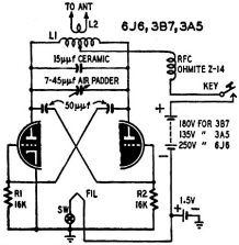
Fig. 5 - Schematic of the transmitter. For a 6J6, heater battery should be 6.3v.
The relay used in the receiver is a Sigma 4F, 8,000-ohm unit, obtainable on the
surplus market or from Control Research Co., P.O. Box 9, Hampton, Virginia, who
carry other radio control supplies and specialize in kits for radio-control equipment.
This relay is the heart of the set and must be super-sensitive and have adjustable
contact spacing and armature spring tension.
Adjust the relay to pull in the armature at 1.1 ma and release it at 0.7 or 0.8
ma. The armature spring tension and contact spacing must be reduced from the original
settings. The contact spacing should not be over 10 one-thousandths of an inch to
start with, and the armature must not touch the pole piece when pulled in.
The control units may be of the escapement type, pulse type (which rotates back
and forth 180°), or small electric motors with self-centering limit switches.
These may be covered in a future article.
The escapement shown in Fig. 4 is also from Control Research Co., available in
kit form. The dimensions shown will produce a slightly larger unit with more reliability
for operation in a large plane or boat model. This unit should weigh from 1/2 to
1 ounce completed.
The escapement is wired to the relay so the relay opens the circuit when energized
by the no-signal plate current. The circuit closes when the relay opens as a signal
is received. A s.p.s.t. switch is required in the escapement circuit to open the
circuit when the receiver is turned off.
The batteries used are a factor in weight. Eveready 413E B-batteries will last
three to four months, and two penlite batteries in parallel will provide filament
current for a month or more. The batteries used to control the escapement or control
unit draw the most current and should be as large as possible. The author uses four
to six penlite batteries in series-parallel to develop 3 volts. They are usually
good for 12 to 20 flights of 5 to 10 minutes duration each. The weight of the complete
installation with above batteries will be about 12 ounces. Smaller batteries may
be used to reduce weight, with a corresponding reduction in life and reliability.
The transmitter, diagrammed in Fig. 5, is a conventional push-pull circuit and
may use a 3A5 or a 3B7. A 6J6 may be used if operation from a car battery is desired.
The author started with a dry-battery-operated 3A5 unit but now uses a 6J6 transmitter
with a surplus-bargain dynamotor for B-supply. Both units were equally reliable,
but the dynamotor eliminates the worry of battery drain affecting signal strength.
The grid-leak resistors R1 and R2 shown in Fig. 5 were reduced to 6,800 ohms
for the 6J6 to increase output.
The transmitter is constructed on the U-frame part of a standard 2 1/4 x 2 1/4
x 5-inch aluminum box, as shown in the photo above. The tube socket is at the bottom
of the U with the tube outside for better cooling.
The control switch in the B plus lead can be any type of push-button switch mounted
either on the transmitter or at the end of a 5- or 6-foot cord to permit moving
around while operating.
The r.f. choke is an Ohmite Z-14, but one similar to the type used in the receiver
will do as well. L1 is 9 turns of No. 16 center-tapped, with an inside diameter
of 3/4 inch. Turns are spaced one wire diameter. L2 is 1 1/2 turns with 3/4-inch
inside diameter.
A folded dipole antenna has been found to be the most effective for transmission
over distances up to three miles. The dipole is a piece of 300-ohm ribbon line 14
feet, 5 inches long, shorted at the ends. A 300-ohm lead-in connects to the center
of one of the antenna conductors. The mast must be mounted in a piece of pipe or
other support to permit rotation. A 9-foot vertical rod antenna may also be used
if operation is limited to ranges of one-half mile or less. One side of L2 is grounded
when using this type of antenna.
Tune the transmitter with an absorption-type wavemeter or grid-dip meter and
then tune the receiver to the transmitter frequency as described above.
The transmitter and receiver circuits shown may be used also for operation in
the 50- to 54-mc amateur band with the advantage of shorter antennas.
The equipment described above provides an excellent beginning for the newcomer
to radio control. The author wishes to thank the Control Research Co. for permission
to use the transmitter schematic and the receiver circuit (as modified by the writer
with the spiral coil).
Posted June 9, 2022
|