|
January 1939 Radio-Craft
 [Table
of Contents] [Table
of Contents]
Wax nostalgic about and learn from the history of early electronics.
See articles from Radio-Craft,
published 1929 - 1953. All copyrights are hereby acknowledged.
|
In 1938, Bell Telephone Laboratories,
Western Electric Company, United Air Lines, and Boeing worked together to developed
the first practical microwave radio altimeter for use in commercial aircraft. The
system reported in this 1939 issue of Radio-Craft magazine
is not a radar unit in that the distance is not determined solely by emitting a
signal and measuring the time taken to the target (the ground in this case) and
back again. Rather, the radio altimeter relies on a heterodyned beat frequency generated
between a reference signal and that of the transmitted and received ground-directed
signal. Author Washburn does a nice job explaining the process, so I needn't add
to it. It is interesting to note the statement about the 500 MHz used being
the "highest frequency ever to be used for practical purposes."
New Radio Altimeter Increases Air Safety
News flash: "Wreckage of plane found on side of mountain
by searching party. All aboard apparently instantly killed."
Last month radio helped immeasurably to promote aviation safety. A great laboratory,
a great industrial plant, and a great airline combined to develop, build and test
an altimeter, for use on airplanes, that accurately indicates height above land-level
(including buildings and bridges).
R. D. Washburne
How many times have you read some such tragic report as the above, in connection
with an airplane crack-up on a mountain? Published figures place this general type
of plane casualties at about 50 per cent; imagine it - one-half of all plane crashes
in which, due mainly to poor visibility (fog, etc.) , the "ship" smacked head-on
into obstructions of which the pilot was unaware. Too frequently its passengers
and crew have passed into Eternity.
Achilles' Heel
How could such a catastrophe occur? The motor was working perfectly; the pilot
was experienced and trustworthy; the radio equipment and flying instruments were
in perfect working order - except that the altimeter locked in position by the impact
indicated a height of several thousand feet!
Ah!-There is the answer. Several thousand feet - above sea level... but
the plane was flying in mountainous country and the altimeter did not, could not,
indicate height above land.
The aeronautic-type altitude indicator operates on the principle of the aneroid
barometer. This type of instrument indicates height (altitude) with respect to a
reference level having constant barometric pressure - a condition which is found
only at sea level.
Engineers have worked unceasingly to develop an altimeter that would indicate
height above land with the same or greater accuracy now possible over water (or
land at water-level).
Demonstration
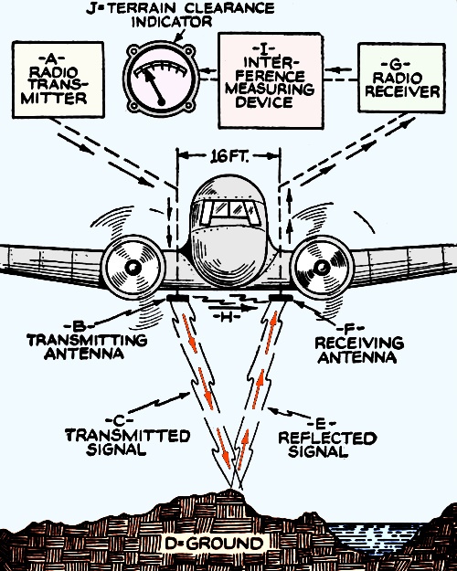
Fig. 1 - Signal C and reflection E, are shown beamed, only
for purposes of illustration. Actually, they are only semi-directional. Antennas
B and F are each 1 ft. long. This radio altimeter is effective from heights of 100
to over 10,000 ft.
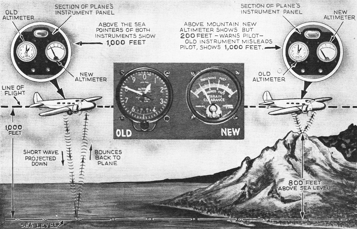
Last month radio as shown in the heading illustration solved the problem. The
radio-operated "Terrain Clearance Indicator" proved its ability in direct comparisons
with the Standard Altimeter; the panel meters of both systems were mounted side-by-side
as shown in Fig. A (insert, in heading illustration).
Bell Telephone Laboratories developed this microwave radio altimeter, Western
Electric Co, made the equipment, and United Air Lines installed the apparatus in
a special Boeing twin-engined airliner. In cooperation, these 3 groups demonstrated
the efficiency of the new radio altimeter in a test flight over New York.
Despite weather conditions or poor visibility, the pilot could read his height
directly and accurately whether he was several thousand feet high or merely skimming
a few feet above the earth.
So keen is the sensitivity of the new altimeter that, from an altitude of several
hundred feet, the presence of the George Washington Bridge was clearly indicated
by the meter as the test ship flew down the Hudson River, far above the actual obstruction
itself. Over the Hudson River both altimeters indicated a height of about 800 ft.;
when the plane swung over the Palisades, the standard altimeter continued to show
a height of 800 ft. but the Radio Altimeter indicated the fact that the ground was
only 250 ft. below the plane!
(No comment has been forthcoming as yet concerning provisions for indicating
conditions dead-ahead - an abruptly-rising plateau, for instance - but undoubtedly
means will be found to take care of this condition. -Author)
Extended flight tests of the new development are being made over regular airways
by engineers of Bell Telephone Laboratories in a special Boeing twin-engined airliner
assigned by United for service testing.
The principle of operation, shown in a general way in Fig. 1, is as follows:
A frequency-modulated, 500-megacycle (0.6 meter) signal - highest frequency ever
to be used for practical purposes, it is said-from a transmitter (A) is radiated
from antenna No. 1 (B) as signal C to ground (D). The reflected signal (E). is picked
up by antenna No.2 (F) connected to a receiver (G).
Although antenna No.1 is directive toward the ground a considerable amount of
energy "slops over" to antenna No. 2 (note direction of arrow, H).
This "slop-over" signal combines with the reflected signal and, in receiver G,
produces a beat frequency which is segregated by an "interference measuring device"
(I) and indicated on a unit, on the instrument-panel in front of the pilot, called
a "terrain clearance indicator" (J).
The beat frequency is a function of the height, .and directly proportional to
it. Therefore the radio altimeter (J) is calibrated for direct-reading in feet.
In order to understand how this radio altimeter functions it may be well to mention
some of the principles previously employed.
Prior Art
(1) The idea of measuring the capacity between airplane and ground is not considered
practicable due to the fact that capacity variation is large for low altitudes but
very small for high altitudes. (2) The principle of measuring the phase difference
between a radiated wave and its reflection is difficult to realize in practice.
(3) The scheme of sending an impulse and then determining the distance as a function
of the elapsed time before the reflection (echo) is received although useful in
measurement of ionosphere heights is not applicable for short distances because
of the minute time element involved. (4). The frequency-modulator radio wave principle
- and the one upon which the new system is based - affords a continuous and linearly
proportional indication of altitude.
Merely to mix, at the receiver, original and reflected signals of the same frequency
(since there would be no change in frequency due to reflection from the ground)
would not produce a beat.
Audio Example
This is easy to understand if we take the example of a person whistling a single
note uninterruptedly. Unless the continuous whistle is interrupted for a certain
length of time it is not possible to hear an echo (reflection) should one exist.
Interrupting the whistle and noting the lapse of time until the echo is heard may
be taken to represent the impulse method of determining distances.
Let us suppose that instead of a continuous single note, a continuous sequence
of notes is whistled. To make the point more clear let us suppose that the note
is warbled up and down the scale, considering however, that in warbling only 2 notes
are sent out.
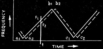
Fig. 2 - The frequency-modulated signal is reflected.
First we whistle note No.1; then, 2nd, note No.2; 3rd, No.1 again; 4th, No.2
again, and so-on. Now, if we are far enough from a reflecting surface so that note
No. 1 reaches our ear as an echo just as note No. 2 is being whistled we will be
able to hear not only both notes simultaneously but also a 3rd or beat frequency
due to the heterodyning (mixing together) of notes 1 and 2. Without going into too
much additional detail let us take for granted that a meter arranged to show the
presence of these beats could be calibrated to indicate the number of feet that
note No.1 had to travel before it heterodyned with note No.2; for maximum indication
on the "beat" meter this will always be a fixed distance.
How then can we obtain beats whose readings on the beat-meter will be equivalent
to other distances?
Frequency Modulation
Well, let us consider a second example in which we wobble the frequency. 5 notes
up and down the scale instead of warbling only 2 notes. The note sequence would
then look like this: No. 1-2-3-4-5-4-3-2-1-2-3-4-5-4-3-2-1-, etc.
Now, if, at the time note No. 4, let us say, is being sent out, note No. 1 is
received, it indicates that the sound had to travel so far to produce an echo that
a 4-note lag resulted; and since each additional note lag means the sound had to
travel just that much further before the echo could be observed, a "lag meter" indicating
this degree of lag - or difference between radiated and received frequencies - could
be calibrated to read directly in feet distance. This "lag" may be compared to the
"beat" mentioned in the 1st example; the beat frequency (lag) therefore is a direct
indication of the echo distance.
This becomes quite clear upon observing that, when note No.5 is radiated and
note No.2 is being received, there i still a difference of 4 notes; that is, the
echo distance has not changed, hence, the feet-distance (beat frequency) indication
remains unchanged.
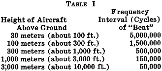
Applying this crude simile to the radio altimeter, let us consider that the 500-megacycle
signal is "wobbled" or frequency modulated. That is, shifted up and down the radio
frequency (wavelength) scale, smoothly and continuously.
The various beat frequencies then required to indicate equivalent echo distances
(or, in the instance of airplane operation, altitude above ground, or a bridge,
a building, or any other reflecting surface) are as given in Table 1. The figures
are from patents issued to Lloyd Espenschied and assigned to American Tel. &
Tel. Co.
With this introduction we are prepared to consider a graph, Fig. 2, which
has been made available by Western Electric Co. This figure illustrates the basic
principle of reflecting a frequency-modulated radio wave (the speed of which is
constant) and indicating the elapsed time as proportional distance.
If an airplane is equipped with a radio oscillator whose frequency can be "wobbled"
according to the sawtooth curve a1 b1 c1 of Fig. 2, and if a corresponding
wave is radiated toward the ground, some of the energy will be reflected back to
the plane where it will set up a current in an antenna. The frequency of that current
will have a similar wobble, but displaced in time to the position a2 b2 c2 by reason
of the delay in travel to the ground and back. At any instant the frequency of the
received wave will differ from that sent out by a constant amount equal to p1 p2.
If the ground falls away or the plane rises, the travel time will be increased
and the received current will be displaced still further; consequently, the frequency
difference at any instant will increase in proportion to the change in clearance.
The difference in frequency between 2 currents can be measured by passing them
through a modulator tube, and measuring the frequency of the "difference" component
in a frequency meter. The scale of this instrument is then graduated in feet, and
indicates directly the terrain clearance.
Transmitter and Receiver
Some idea of how microwave signals may be generated and frequency-modulated at
the transmitter, and the reflected and "slop-over" signals received and the beat
frequency detected and made to indicate on a meter calibrated in altitude at the
receiver, may be obtained by reference to Fig. 3. These illustrations are based
in part on figures in an article, by Sadahiro Matsuo (Faculty of Engineering, Tohoku
Imperial University, Sendaishi, Japan), on a radio altimeter, in a recent issue
of Proc., I.R.E.
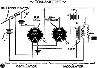
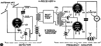
Fig. 3 - (Above & Below) These theoretical, composite
diagrams illustrate the sequence of operations. The frequency-modulated signal results
in a beat frequency that may be resolved on an output meter into terrain clearance
indications in feet.
Referring to Fig. 3A the sawtooth-wave-form modulation, shown in Fig. 2,
is obtained from modulator V2 and applied in required degree to the grid of V1.
(Note - Matsuo's transmitter employed V1 as a Barkhausen-Kurtz triode oscillator.
-Author)
In Fig. 3B, the beat-frequency signal is detected, amplified, limited to
a constant value, and applied to an output meter (altitude indicator). In order
to secure satisfactory operation of an indicator-type frequency meter, with a constant-output-level
beat frequency input, inverse voltage is fed to tubes V4-V5 by connecting transformer
secondaries Sec. 1 and Sec. 2 as shown. Tubes V4-V5 alternate in conductivity.
In addition to the regular meter, the device may also be equipped with a red
signal light which will automatically flash a warning when the plane descends below
a safe predetermined altitude.
This radio distance indicator may also be used on shipboard. In foggy weather
the presence of icebergs, other ships, promontories, etc., could be detected and
their exact distance indicated.
In commenting on this latest scientific tool for aeronautical navigation, W.
A. Patterson, President of United Air Lines, said, "Our engineers and pilots regard
the development of this device as one of the most important technical advancements
in the history of air transportation, and a major contribution to the safety of
scheduled flying. Following completion of service tests now in progress with the
device in United's Flying Laboratory, we will make these devices standard equipment
on every airliner in our fleet."
|