|
|||||||||||||
 |
|||||||||||||
The "Monode" Noise Generator
|
|||||||||||||
Calibrated noise diodes are fairly inexpensive these days and are widely used for measuring noise figure of systems and for generating specific signal-to-noise ratios when testing receiver performance. This article from a 1967 edition of the ARRL's QST magazine describes a method for using a "hot resistor," aka "monode," as a noise reference source. When the temperature (T) and the resistance (R) is known, a noise power can be calculated with a precision limited by the precision of the T and R measurements. In this case the tungsten filament of a pilot lamp is used as the resistor. Interestingly, if you do an Internet search for the term "monode," the only thing that returns are references to this article. Per the author, "The term 'monode' is derived from vacuum-tube terminology, a monode being a one-element vacuum tube." There is a company that goes by the name Monode. Hot-Resistor Noise-Figure Measurement
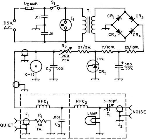
Fig. 1 - Circuit of the Monode noise generator. Except as indicated, capacitances are in µf.; capacitor with polarity marked is electrolytic, other fixed capacitors are disk ceramic. Resistances are in ohms. C1 - Ceramic trimmer (Centralab 822-EN or equivalent). See text
for values for frequencies other than 144 Mc. By Ronald E. Guentzler, W8BBB This article describes a noise generator that should find use in amateur work either as a noise source for noise-figure measurements or as a reference source for comparison with the output from some other noise source. It is inexpensive and simple to construct. The "Monode" noise generator is essentially a hot resistor whose noise output is known when the temperature and resistance are known.1 The hot resistor is the tungsten filament of a No. 12 radio pilot lamp heated from a d.c. source. The term "Monode" is derived from vacuum-tube terminology, a monode being a one-element vacuum tube. The Monode noise generator was constructed to obtain a known source of random noise to check the performance at 147 Mc. of a 5722 temperature-limited diode generator similar to the one in the Handbook.2 The reason for desiring a means of checking the 5722 generator arose from comments by J. A. Huie3 and A. van der Ziel4 regarding the effects of stray capacitance and inductance on the noise output of the 5722 generator at high frequencies. (The output of a 5722 generator was found to be 12 percent or 0.5 db. high at 147 Mc. before compensation!) Two other Monode noise generators were built to prove that the principle of the Monode noise generator was indeed practical at lower frequencies. These generators are for use in the 6- and 40-meter bands. The Resistor as a Noise Generator A resistor at any temperature above absolute zero generates a noise power P = KTB watts, where K = 1.38 X 10⁻²³ Joules/Kelvin degree, T is the temperature of the resistor in degrees Kelvin, and B is the bandwidth in cycles per second. When the temperature of a resistor is other than some reference temperature, T0 (usually taken as 290°K), it may be convenient to use the terms "excess noise temperature" or "excess temperature," which are defined as the temperature of the resistor minus reference temperature; i.e., TE.N. = T - T0. The term "excess noise" is commonly used; the excess noise is the excess noise temperature divided by the reference temperature; i.e., E.N. = (T - T0) /T0. A resistor is about as basic a noise generator as you can get. The filament temperature of a No. 12 dial lamp can be adjusted to the desired resistance with sufficiently high noise output, and the corresponding noise temperature is available from the calibration curve given in this article. With these data, measurement of receiver noise figure becomes simple. The excess noise may be given in db., where E.N.db. = 10 log10 (T - T0) /T0. In order to obtain enough noise for convenience of measurement, the resistor may be raised to many times room temperature. The filament of an incandescent lamp makes a good hot resistor because tungsten is a well-behaved material and has a high melting point. The temperature can be raised by passing a direct current through it. The Monode Generator The Monode has the advantages of simplicity, low cost, and being an absolute standard. The disadvantages are fixed output and the necessity for tuning each amateur band (but not within the band). The complete generator is composed of three basic parts: a regulated variable-voltage power supply, a room-temperature "quiet" termination (R1), and the noise generator with its r.f. filtering and coupling network (Fig. 1). The variable d.c. voltage from the power supply is used to heat the filament of the lamp. The d.c. is filtered by means of RFC1 and a 0.001-µ.f. capacitor, C3, to eliminate any r.f. noise component that might be present in the power supply. RFC2 is used to conduct into the lamp the d.c. required to heat the filament while preventing the thermal noise generated in the hot lamp filament from being lost in the supply. The noise generated in the filament is coupled to the output connector, J2, by means of C1; this capacitor also serves the function of resonating the lead and lamp-filament inductances so that the output impedance is purely resistive.
Fig. 2 - The noise- generating head of the Monode. Leads between the lamp, C1 and the coax connector are kept to the shortest possible length. The quiet termination and r.f. filter are in a similar box bolted to the bottom of the one shown.
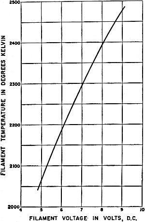
Fig. 3 - Filament temperature in degrees Kelvin vs. applied d.c. voltage, G.E. No. 12 pilot lamp. Construction The major portion of the noise generator can be built using any mechanical construction desired. The one described was built on a 3 1/2 X 19-inch relay-rack panel. The power supply is mounted in a 3 X 4 X 6-inch aluminum chassis fastened to the rear of the panel. The r.f. filter network and the quiet termination, R1, and its connector, J1, are mounted in a small Minibox. The No. 12 lamp, C1, RFC2 and J2 are mounted in an identical Minibox. The two Miniboxes are fastened together and to the panel; the connectors J1 and J2 protrude through holes in the panel. One obvious innovation would be to have the Minibox containing the lamp physically separate from the power supply and connected to it by means of a flexible cord. In this event, the coaxial socket J2 would be replaced by a plug and R1 would be mounted in a separate plug. The power supply is a conventional bridge-rectified, RC-filtered supply with a shunt Zener regulator. The supply was made electrically larger than necessary because it was not known at the time of construction what lamp type would be used in the final version. The 1/2-ampere, 18-volt capability gives a range of voltages and currents large enough for experimental purposes. The actual maximum output required for the No. 12 lamp is 10 volts at 200 ma. The regulation is probably not necessary. The noise-generator portion of the unit requires more than usual care, considering the frequency for which the unit is designed. Stray inductance and capacitance are not particularly important, although they should be kept low; this is the opposite of the 5722 generator where stray inductance and capacitance result in improper amounts of noise output. However, losses cannot be tolerated; i.e., any resistance appearing in the noise-generating circuit other than the hot lamp filament must be eliminated. This is again the opposite situation from the 5722 generator where losses will, in general, have no deleterious effects and can be beneficial. Fig. 2 is a photograph of the noise-generating portion of the unit. The components are mounted in such a way that the lead lengths are as short as possible in order to keep their losses low. The lamp is mounted in a "socket" constructed from two of the metal inserts taken from a miniature-tube socket. An entire tube socket cannot be used because the pin spacing is improper. Also, sockets introduce the possibility of losses. The Monode described here is usable at frequencies below 144 Mc. with slight modification. Two separate noise-generating portions were built, one for use on 6 meters and one for use on 40 meters. For 6 meters, C1 is a 50-380-pf. mica trimmer, RFC1 and RFC2 are Ohmite Z-50 inductors, and C3 is the same as listed for 2 meters. For 40 meters, C1 is two 0.001-µf. fixed mica capacitors in parallel, RFC2 is an Ohmite Z-7 inductor, RFC1 is omitted, and C3 is a 0.1-µf. ceramic. For the other high-frequency bands, use the appropriate Ohmite inductor for RFC2, omitting RFC1; use a 0.1-µf. disk ceramic for C3. C1 should be the size required to resonate the lamp filament and lead inductance in order to present a pure 50 ohms at the output connector. Adjustment Although the temperature of the lamp filament can be varied by varying the applied .c. voltage, only one temperature of operation is usable because the resistance of the filament is also a function of the applied voltage, and this resistance must be set to give the proper output impedance. Some means of impedance measurement in the band in which the unit is to be used should be available; this can be either an impedance bridge or meter or an s.w.r. bridge known to be properly calibrated. The impedance-measuring device must be sensitive enough to operate on small amounts of r.f. This is necessary to insure that the r.f. getting into the lamp does not heat the filament to a temperature greater than that resulting from the applied d.c. A good check can be made by applying the r.f. while the d.c. is off. The lamp should not glow. With the impedance-measuring device connected and operating, the d.c. lamp voltage is applied and the voltage and C1 are adjusted until the output impedance at connector J2 is 50 ohms, purely resistive. The value of the lamp voltage is noted, and whenever the unit is to be used the voltage is set at this value. If the Monode noise generator is to be used as a reference for comparison with other noise generators, it is important that the output impedances of all the generators be the same. The best way to make sure that they are the same is to measure all of them at the same time, with the same measuring device, and at the same frequency. The operating temperature of the filament can be found from Fig. 3. This curve applies to General Electric No. 12 lamps, and may not be applicable to lamps of other than G.E. manufacture.5 The excess temperature or excess noise can be calculated by means of previously given formulas. For example, assume that as a result of the impedance adjustment step it was found that the lamp must operate at 8.4 volts in order to give an output impedance of 50 + j0. With the aid of Fig. 3 the lamp temperature is found to be 2430°K when operated at 8.4 volts. This is the noise temperature. If room, or reference, temperature is 290°K, then the excess temperature is 2430 - 290 = 2140°K, and the excess noise in db. is 10 log10 (2140/290) = 8.7 db. R1 should be adjusted to give an impedance of 50 + j0 when viewed through J2 This resistor should be an inherently nonreactive composition type such as the Ohmite "Little Devil." Using the Monode Generator In using the Monode as a source of noise for noise-figure measurements of a receiver, the quiet termination of the Monode is first connected to the input of the receiver under test by means of a coaxial cable having x db. loss. (If the separate noise-head construction is used, x is taken as zero.) The output noise power from the receiver is noted; call this reading A. The Monode is then set to its operating voltage, its output is connected to the input of the receiver through the same cable, and the output power of the receiver is noted; call this reading B. The noise figure of the receiver in db. is then found from the formula N.F.db. = E.N.db. - x - 10 log10 (A-1), where E.N.db. is the excess noise of the Monode noise generator in db. Note that B and A must be in units of power and not in db. For example, assume that a coaxial cable with 0.9 db. loss is being used between the Monode noise generator and the receiver; this makes x = 0.9 db. Assume that the excess noise of the Monode is 8.7 db. (from the previous example). Further, assume that the receiver noise output was 1 milliwatt with the quiet termination and 4 milliwatts with the Monode connected; this makes B/A = 4. Therefore, the receiver noise figure is 8.7 - 0.9 - 4.8 = 3.0 db. Concluding Remarks The following comments are intended to provide a basis for further experimentation, especially at frequencies above 150 Mc. Skin effect does not significantly increase the a.c. resistance of the lamp filament from the d.c. value, at frequencies up to 150 Mc., because the filament diameter is small (approximately 0.001 inch) and the resistivity of tungsten is relatively high. Therefore, it would be expected that the resistive component of the output impedance as seen from J2 would be the same as the d.c. filament resistance as calculated by taking the ratio of the lamp voltage and current. However, there is about 1 pf. shunt capacitance across the lamp resulting from the lamp leads, and there is a significant amount of inductance effectively in series with the filament resistance. This inductance is principally a result of the coiled filament and the filament support leads; the total inductance is approximately 0.04 microHenry. As a result of the inductance and capacitance, the resistive portion of the filament impedance, as viewed from J2, is increased in magnitude. This increase is significant only at 50 Mc. and above. For the unit pictured in Fig. 2, the d.c. lamp resistance is 45.6 ohms when the output impedance is 50 + j0 at 147 Mc. The impedance step-up effect was not observed in an earlier version of this unit. The d.c. filament resistance and the output impedance were both 50 ohms. This was considered a bit of good luck until the noise output was found to be too low. It was discovered that the inductor RFC2 was lossy and, since it was effectively in parallel with the lamp, its associated losses lowered the apparent filament resistance, the output impedance, and the noise temperature. This is why the Ohmite inductors are specified. A different lamp type might eliminate the impedance transformation problem and the necessity for retuning or rebuilding the Monode noise generator for each different amateur band. An ideal lamp type for noise generation would be one with a straight (not coiled) filament mounted in a small-diameter tubular bulb having the lead-in wires appearing at the opposite ends of the lamp. If the leads are brought out from opposite ends of the bulb, the lamp could be coaxially mounted. This mounting scheme offers the possibility of low stray inductance and capacitance. I wish to express my appreciation to Mr. Donn R. Hobbs of the Miniature Lamp Department, General Electric Company, Nela Park for many pieces of information regarding miniature lamps. 1 A. van der Ziel, Noise, Prentice-Hall, 1954, pp. 60-61. 2 The Radio Amateur's Handbook, 42nd ed., 1965, pp. 527-528. 3 Huie, "A V.H.F. Noise Generator," QST, Feb. 1964, 4 A. van der Ziel, op. cit., pp. 63-69. 5 Smithsonian Physical Tables, 9th ed., rev. 1956, Table 85 and Test No. 7824, Miniature Lamp Dept., General Electric Co., Nela Park, 1966.
Posted May 16, 2023 |
|||||||||||||
 |
|||||||||||||
|
|||||||||||||


|
||||||||||||||||||||||||||||||||||||


