Module 21 - Test Methods and Practices |
||||||||||||||||||||||||||||||||||||||||||||||||||
|
Module 21 − Test Methods and Practices
Pages i , 1−1, 1−11, 1−21, 2−1, 2−11, 2−21, 2−31, 2−41, 3−1, 3−11, 3−21, 3−31, 4−1, 4−11, 5−1, 5−11, 5−21, 5−31, AI−1 to AI−3, Index
Warning
Exercise caution in using a stroboscope. The illusion of stopped motion is very convincing. Do not attempt to touch the moving equipment.
Q-19. If you are required to monitor the speed of a device with a stroboscope over an extended period of time, what step should be taken to prolong the life of the flasher tube?
Frequency Counter Methods
Various frequency counters have found application as an ELECTRONIC TACHOMETER to obtain accurate measurements of high-speed rotating machinery. a tachometer pickup may be used to produce signals that are fed directly to the frequency counter. If the tachometer pickup is designed to generate 1 signal per revolution, the counter will indicate directly in revolutions per second; if the pickup is designed to produce 60 signals per revolution, the counter will indicate directly in revolutions per minute.
Audio-Frequency MEASUREMENTS Audio-frequencies can be measured with a variety of nonelectronic and electronic devices. Examples of nonelectronic measuring devices are the vibrating-reed meter and the moving-disk frequency meter. (Both of these devices were discussed in NEETS, module 3.) They are used primarily to measure the frequency of ac power, 60 Hz. However, such instruments do not have a wide frequency range. The most common instruments available for the measurement of audio frequencies are oscilloscopes and frequency counters.
OSCILLOSCOPE METHOD
The frequency of a waveform can readily be determined by using an oscilloscope. The most common oscilloscope method of measuring a frequency is accomplished by first measuring the time duration of the waveform. Frequency is the reciprocal of time
and may be easily computed, as shown in figure 3-24.
3-31
Figure 3-24. - Oscilloscope method of determining frequency.
Another common method of determining the frequency of a waveform is by using Lissajous patterns. This method was discussed in NEETS, module 19.
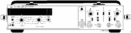
Frequency COUNTER METHOD
While oscilloscopes can be used to compare rectangular waveforms for the purpose of measuring the frequency of a signal, frequency counters, as shown in figure 3-25, are much more useful for this purpose. The fundamental measurement of frequency is accomplished by totaling the number of cycles into the counter for a precise period of time. The result is then displayed as an exact digital readout. The audio- frequency signal must be of sufficient amplitude to trigger the counter. The AUTO-MANUAL switch provides two methods of frequency counter operation. One method is to initiate the count simultaneously with the initiation of the signal to be measured. With this method, the AUTO-MANUAL switch should be set to the MANUAL position. The second method assumes that the signal to be measured has been operating over some indefinite period of time and that it will continue to do so after a measurement has been taken (hence, only that segment of the signal required to make the frequency measurement is important). With this method, the AUTO-MANUAL switch is to be set to the AUTO position.
3-32
Figure 3-25. - Frequency counter.
Radio-Frequency (RF) MEASUREMENTS
Radio-frequency measurements are primarily made with frequency counters. Most oscilloscopes are limited in use to approximately 100 MHz. Frequency meters, such as the Hewlett-Packard 530 series, are widely used but lack the accuracy of frequency counters. Frequency Meters
Prior to the invention of the frequency counter, most frequency measurements above the af range were made primarily with frequency meters.
This process involved heterodyning the frequency to be measured against the calibrated output of the frequency meter to obtain a zero beat from which the measured frequency was then read. This method proved inaccurate because of reading errors.
Frequency meters as we know them today are entirely different from their predecessors. Today's frequency meters (fig. 3-26) contain waveguide or coaxial lines coupled to quarter-wavelength resonant cavities. The meter is adjusted until the cavity is tuned to the resonant frequency of the signal being measured. At resonance, power is absorbed by the cavity and produces a dip in the output-power level, as measured at the frequency meter's output connector. The resonant frequency is read directly from the frequency meter dial and is accurate, in most cases, to approximately ±0.2%. Frequency meters are capable of measuring frequencies in the range of 1 to 40 gigahertz, far exceeding the frequency limitations of the average frequency counter.
Q-20. What happens when a frequency meter is adjusted to the frequency of the signal being measured?
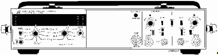
3-33
Figure 3-26. - Frequency counter.
Frequency Counters
In the early 1950s, the frequency counter was developed. The device could measure and accurately indicate frequencies up to 10 MHz. Present-day frequency counters can accurately read frequencies as high as 40 GHz. In addition to direct frequency measurement indication, some types of frequency counters can measure the WAVE PERIOD, which is the inverse of frequency; RATIO, which compares one frequency against another; and TIME INTERVAL, the time between two events or the time between two functions of an event. In addition, frequency counters can totalize event indications. This is similar to measuring the frequency except that a manual or an electronic start-stop gate controls the time over which the measurement is taken. Frequency counters can also provide scaling in the form of a digital output signal from the frequency counter that represents a frequency-related division of the input frequency.
All of the above functions have useful applications. For pulse timing, the period function is used; totalizing is used in digital applications; and ratio is used in comparing harmonic-related signals. Scaling is used for triggering other test equipment used in conjunction with the frequency counter; and time- interval capability is used in measuring the interval between two pulses or between two sets of pulses. Because of the wide variety of frequency counters in use, the technical manual for a specific frequency counter should be consulted to determine the instrument's full capabilities.
Frequency Counter Accuracy
All frequency counter measurements are measured with 1 part in 108 of accuracy. However, frequency counters have provisions for input from external frequency standards. This extends the accuracy of the frequency to that of the standard. a frequency self-check capability is provided to determine if the counting and lighting circuits are operating properly.
3-34 Wavemeters
Wavemeters are calibrated resonant circuits used to measure frequency. Although the accuracy of wavemeters is not as high as that of heterodyne frequency meters, they have the advantage of being comparatively simple and can be easily carried about.
Any type of resonant circuit may be used in wavemeter applications. The exact kind of circuit employed depends on the frequency range for which the meter is intended. Resonant circuits consisting of coils and capacitors are used for low-frequency wavemeters. Butterfly circuits, adjustable transmission line sections, and resonant cavities are used in vhf and microwave instruments.
There are three basic kinds of wavemeters: the absorption, the reaction, and the transmission types. Absorption wavemeters are composed of the basic resonant circuit, a rectifier, and a meter for indicating the amount of current induced into the wavemeter. In use, this type of wavemeter is loosely coupled to the circuit to be measured. The resonant circuit of the wavemeter is then adjusted until the current meter shows a maximum deflection. The frequency of the circuit under test is then determined from the calibrated dial of the wavemeter.
The reaction type derives its name from the fact that it is adjusted until a marked reaction occurs in the circuit being measured. For example, the wavemeter is loosely coupled to an oscillator, and the resonant circuit of the meter is adjusted until it is in resonance with the oscillator frequency. The setting of the wavemeter dial is made by observing the output current of the oscillator. At resonance, the wavemeter circuit takes energy from the oscillator, causing the current to dip sharply. The frequency of the oscillator is then determined from the calibrated dial of the wavemeter.
The transmission wavemeter is an adjustable coupling link. When it is inserted between a source of RF energy and an indicator, energy is transmitted to the indicator only when the wavemeter is tuned to the frequency of the source. Transmission wavemeters are widely used in measuring microwave frequencies.
In figure 3-27, a typical cavity wavemeter is illustrated.
3-35
Figure 3-27. - Typical cavity wavemeter.
The wavemeter illustrated is of the type commonly used for the measurement of microwave frequencies. The device employs a resonant cavity, which effectively acts as a high-Q LC tank circuit. The resonant frequency of the cavity is varied by means of a plunger that is mechanically connected to a micrometer mechanism. Movement of the plunger into the cavity reduces the cavity size and increases the resonant frequency. Conversely, an increase in the size of the cavity (made by withdrawing the plunger) lowers the resonant frequency. The microwave energy from the equipment under test is fed into the wavemeter through one of two inputs, a or D. a crystal rectifier then detects or rectifies the signal, and the rectified current is indicated on the current meter, M.
The instrument can be used as either a transmission type or an absorption type of wavemeter. When used as a transmission wavemeter, the unknown signal is coupled into the circuit by means of input A. When the cavity is tuned to the resonant frequency of the signal, energy is coupled through coupling loop B into the cavity and out through loop C to the crystal rectifier where it is rectified and indicated on the meter. At frequencies off resonance little or no current flows in the detector and the meter reading is small. Therefore, the micrometer and attached plunger are varied until a maximum meter reading is obtained. The micrometer setting is then compared with a calibration chart supplied with the wavemeter to determine the unknown frequency.
When the unknown signal is relatively weak, such as the signal from a klystron oscillator, the wavemeter is usually used as an absorption type of device. Connection is made to the instrument at input D. Rf loop C then acts as an injection loop to the cavity. When the cavity is tuned to the resonant frequency of the klystron, maximum energy is absorbed by the cavity, and the current indicated on the meter dips. When the cavity is not tuned to the frequency of the klystron, high current is indicated on the current meter. Therefore, the cavity is tuned for a minimum reading, or dip, in the meter; and the resonant frequency is determined from the micrometer setting and the calibration chart.
3-36 The potentiometer, R1, is used to adjust the sensitivity of the meter from the front panel of the instrument. J1 is a video jack and is provided for observing video waveforms with a test oscilloscope.
Summary
The following is a brief summary of the important points of this chapter.
All Impedance BRIDGES have several things in common. Each type of bridge has a comparing circuit and a measuring circuit. They measure an unknown impedance by comparing the characteristics of the device under test with the characteristics of components within the test set.
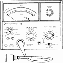
Power METERS that are designed to measure af power can be separated into two distinct groups. Power meters that are designed for measuring sine waves are basically electronic voltmeters calibrated in dB or dBm. VU METERS are designed to measure the average value of complex waveforms, such as a voice.
The most common type of test equipment used to measure RF power is the ABSORPTION Power METER. Absorption power meters are designed to absorb all or part of the signal being measured. Examples of absorption power meters are output power meters, in-line wattmeters, and meters employing bolometers.
3-37
CALORIMETERS are the most accurate type of test equipment used for measuring high power. As power is applied to a calorimeter, its medium (either liquid or solid) is heated. The heat that is produced is directly proportional to the amount of applied power. The amount of applied power is determined by measuring the change in temperature of the medium.
Today's ELECTRONIC Frequency COUNTERS are capable of measuring frequencies from dc to 40 GHz. Most have added features that enable period averaging, time-interval measurements, and scaling. Frequency counter accuracy can be extended by using an external frequency standard in lieu of its internal frequency standard.
REFERENCES
Coaxial Frequency Meter, NAVSHIPS 0969-092-3010, Naval Ships Systems Command, Washington, D.C., 1978.
EIMB, Test Methods and Practices, NAVSEA 08967-LP-000-0130, Naval Sea Systems Command, Washington, D.C., 1980.
Fire Control Technician (M) 3 & 2, NAVEDTRA 10209-A, Naval Education Training and Program Development Center, Pensacola, Fla., 1974.
3-38 NEETS, Module 16, Introduction to Test Equipment, NAVEDTRA 172-16-00-84, Naval Education and Training Professional Development and Technology Center, Pensacola, Fla., 1984.
Answers to Questions Q1 Through Q20.
A-1. a bridge circuit is balanced when the opposite legs of the comparing and measuring circuits exhibit the same voltage drop.
A-2. The capacitive and inductive characteristics of the test leads.
A-3. As the supply voltage increases, bridge components may heat up and become less accurate.
A-4. Small values of resistances.
A-5. a standard capacitor.
A-6. Both measure phase angle and magnitude in determining impedance.
A-7. High VSWR, which equates to poor reception or a loss of power output.
A-8. DB, dBm, and vu.
A-9. 600-ohm load.
A-10. dB meters are used for measuring sine waves. Vu meters are used to measure the average value of complex waveforms.
A-11. Current transformers.
A-12. Electronic wattmeters are capable of measuring high-frequency signals.
A-13. Most in-line wattmeters are capable of measuring both forward and reflected power.
A-14. Temperature-sensitive material that exhibits a large negative temperature coefficient.
A-15. Temperature, mass, and time.
A-16. As power is applied, the medium heats up in proportion to the applied power.
A-17. The National Bureau of Standards.
A-18. They are used to monitor fixed motor speeds.
A-19. Monitor a submultiple frequency to prolong the flasher-tube life.
A-20. Power is absorbed by the frequency meter cavity; and a pronounced dip in power, at the output, will be observed.
3-39
|
||||||||||||||||||||||||||||||||||||||||||||||||||