Module 21 - Test Methods and Practices |
||||||||||||||||||||||||||||||||||||||||||||||||||
|
Module 21 − Test Methods and Practices
Pages i , 1−1, 1−11, 1−21, 2−1, 2−11, 2−21, 2−31, 2−41, 3−1, 3−11, 3−21, 3−31, 4−1, 4−11, 5−1, 5−11, 5−21, 5−31, AI−1 to AI−3, Index
ratio is reached. It must be understood, however, that the antenna does have a specific impedance at a given frequency and that, when necessary, this impedance may be determined by use of an RF impedance bridge.
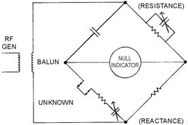
A typical RF impedance bridge circuit is shown in figure 3-9. Rf impedance bridge measurements require an RF signal generator, a detector, and a calibrated RF bridge to determine transmission-line impedance. The bridge compares the parallel resistive-reactive combination with the series combination and can typically measure impedance over a frequency range of 500 kHz to 60 MHz.
Figure 3-9. - Typical RF bridge.
Basically, the bridge is balanced with a known capacitance under short-circuit conditions. The unknown impedance is then inserted in lieu of the short bus, and the bridge is rebalanced. The difference between the known impedance under short-circuit conditions and the balance measurements obtained with the unknown impedance inserted in lieu of the short is the value of the unknown impedance.
Q-7. What is the result of an impedance mismatch between a receiver or transmitter and its transmission line or antenna?
Power MEASUREMENTS
It is often necessary to check the input and output signal power levels of electronic equipment. The determination of dc power is computed by using a derivative of Ohm's law (P = IE = I2R = E2/R). However, the presence of a reactive component in ac circuits means that apparent power is being measured or calculated unless the rms voltage-current value is multiplied by a power factor to obtain true lower. The measurement of ac power is further complicated by the frequency limitations of various power meters. If there is no phase difference, ac power may be computed in the same manner as dc power by determining the average value of the product of the voltage and current. In practical ac circuits, the apparent power must be multiplied by the cosine of the phase angle between the voltage and current in order to compute true power.
In the repeated measurement of audio-frequency (AF) power, you may use a normal power meter calibrated directly in watts. However, when reactive components of dissipative impedance introduce a
3-11 phase angle, a device that is proportional to both the power factor and the apparent power must be used. Because power-level measurements are concerned with decibel units, a working knowledge of decibels is required for proper interpretation of power tests. The decibel is used to determine the ratio of power changes or to indicate the power level in a circuit with respect to either 0 or a standard reference level.
AF Power
In the electrical transmission of speech or music, rapidly fluctuating amplitudes and frequencies are involved. The average power-level measurement and its variation rate depend on the signal characteristics and time interval over which this average is taken. Power measurements for af circuits are usually indicated in terms of decibels (dB), decibels referenced to 1 milliwatt (dBm), or volume units (vu). For example, the power gain of an amplifier can be expressed in dB; the power level of a sinusoidal signal compared to a 1-milliwatt reference is indicated in dBm; and the power level of a complex signal, such as voice, music, or multiplexed information, compared to a reference level of 1 milliwatt, is indicated in vu.
Q-8. What are the three units of measure most commonly used when referring to AF power measurements?
DECIBEL METERS
A dB meter is a form of ac electronic voltmeter calibrated in dB's. These meters are useful for making measurements where direct indication in decibels is desired. However, remember that these are voltmeters, and power measurements are not meaningful unless the circuit impedance is known. When the dB meter is calibrated, a reference point, based on a specific power or value of voltage across a specified resistance, is selected to represent 0 dB. Many electronic voltmeters use a single dB scale based on 1 milliwatt into a 600-ohm load to represent 0 dBm. Based on this reference point, various voltage readings could be made on the low ac-voltage scale. The +dB numbers corresponding to voltage ratios that exist between successive ranges and the low ac range have been computed for each range. These numbers, shown on the front panel of the instrument, are added algebraically to each successive range reading to produce the correct value for the range. The term decibel does not, in itself, indicate power. It indicates a ratio or comparison between two power levels that permits you to calculate the power. Often, it is more desirable to express performance measurements in terms of decibels using a fixed power level as a reference. The original standard reference level was 6 milliwatts, but to simplify calculations a standard reference level of 1 milliwatt has been adopted.
Q-9. In reference to dB meters, 0 dBm represents 1 milliwatt into what value of load?
VOLUME UNIT METERS
The volume unit (vu) meter is used in audio equipment to indicate input power to a transmitter or to a transmission line. This type of meter has special characteristics, such as a standardized speed of pointer movement, speed of return, and calibration. The measurement of the average power level and its rate of variation with respect to time depends not only on the signal characteristics, but also on the time interval over which the average is being taken. Accordingly, the speed of response of the instrument used to measure average power is of particular concern. The unit of measurement is the volume unit (vu), which is numerically equal to the number of dB above or below the reference level of 1 milliwatt into a 600-ohm load (provided the standard instrument was calibrated under constant-amplitude, sine-wave conditions). a change of one vu is the same as a change of one decibel. Therefore, the vu value obtained represents averages of instantaneous power of speech or music obtained by an instrument having particular dynamic characteristics. The vu readings are equivalent to the power level in decibels only if the sinusoidal waveform is of constant amplitude.
Q-10. What is the main difference between a vu and a dB meter?
3-12 ELECTRODYNAMIC WATTMETER
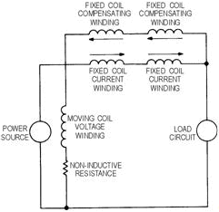
The electrodynamic wattmeter is used to measure power taken from ac or dc power sources. The electrodynamic wattmeter, shown in figure 3-10, uses the reaction between the magnetic fields of two current-carrying coils (or sets of coils), one fixed and the other movable. When the current through the fixed-position field winding(s) is the same as current through the load and the current through the moving coil is proportional to the load voltage, then the instantaneous pointer deflection is proportional to the instantaneous power. Since the moving pointer cannot follow the rapid variations in torque because of its momentum, it assumes a deflection proportional to the average power. The dynamometer-type wattmeter automatically compensates for the power factor error of the circuit under test. It indicates only the instantaneous power resulting from in-phase values of current and voltage. With out-of-phase relationships, a current peak through the moving coil never occurs at the same instant as the voltage peak across the load, resulting in less pointer deflection than when the current and voltage are in phase. The simple meter shown in figure 3-10 is not compensated. When the load is disconnected, this meter will still indicate that power is being consumed in the circuit. This difficulty can be eliminated by incorporating two compensating windings, mounted with the primary fixed-coil current windings, as shown in figure 3-11. These stationary windings are used to produce a magnetic flux proportional to the current through the movable coil. As shown by the arrows, the currents through the primary movable coil and the compensating coil flow in opposite directions, producing a torque caused by the opposing magnetic fields. These opposing fields cancel. Hence, with the load removed from the circuit, the meter will indicate zero power through the load.
Figure 3-10. - Typical electrodynamic wattmeter.
3-13
Figure 3-11. - Electrical equivalent of the compensated electrodynamic wattmeter.
Electrodynamic wattmeters are subject to errors arising from various factors, such as temperature and frequency characteristics and vibration. Heat through the control mechanism can cause the springs to lengthen and lose tension; as a result, deflection errors are produced. Figure 3-12 illustrates the mechanical equivalent of the electrodynamic wattmeter. Large currents within the circuit will also produce errors. Therefore, the maximum current range of electrodynamic wattmeters is normally restricted to about 20 amperes. When larger load currents are involved, a current transformer of suitable range is used in conjunction with the wattmeter. However, a current transformer cannot be used if the ac circuit under test contains a dc component.
Figure 3-12. - Mechanical equivalent of the electrodynamic wattmeter.
The voltage range of wattmeters is generally limited to several hundred volts because of heat dissipation within the voltage circuit. However, the voltage range can be extended by using external voltage dividers. Wattmeters used as laboratory standards have an accuracy of 0.1%, high-grade portable wattmeters an accuracy of 0.2% to 0.25%, and high-grade switchboard wattmeters an accuracy of 1% of
3-14 full-scale value. Because electrodynamic wattmeter errors increase with frequency, they are used primarily for measuring 60-hertz line power. Unshielded electrodynamic wattmeters should not be placed in the vicinity of stray magnetic fields. a wattmeter has current, voltage, and power ratings; therefore, damage may result when any of these ratings is exceeded.
The electrodynamic wattmeter may be converted into an instrument for measuring reactive power by replacing the resistance normally in series with the voltage coil with a large inductance. a 90-degree current lag within the voltage coil provides a direct reading proportional to the reactive power in the circuit. Compensating networks must be used to cause the phase shift to be exactly 90º.
Q-11. What type of device is used to extend the current-measuring capability of electrodynamic wattmeters?
IRON-CORE, COMPOSITE-COIL, and TORSION-HEAD WATTMETERS
Iron-core wattmeters are primarily used as switchboard instruments and employ the induction principle. Voltage and current coils are wound around a laminated iron core shaped to produce a mutually perpendicular magnetic field across an air gap. Eddy currents induced in a thin metal cylinder rotating in this air gap interact with the magnetic field to produce a torque proportional to the instantaneous power. This type of construction provides the advantages of increased operating torque, larger angles of rotation, ruggedness, compactness, and freedom from errors caused by stray fields. It has the disadvantage of a very narrow frequency range.
The composite-coil wattmeter uses the upscale torque, produced by the ac power being measured, in opposition to the torque produced by an adjustable dc current in a set of windings intermingled or wound within the ac windings. Greater reading precision is obtained with this method than is possible with straightforward wattmeters, and errors caused by elasticity of the spring suspension carrying the moving- coil system are avoided. The torsion-head wattmeter is used to restore the movable coil to its original position after deflection and to remove the mutual inductance error.
ELECTRONIC WATTMETER
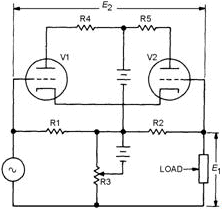
Electronic wattmeters are used for direct, small power measurements or for power measurements at frequencies beyond the range of electrodynamometer-type instruments. a simplified electronic wattmeter circuit is shown in figure 3-13. The matched triodes are operated in the nonlinear portion of their characteristic grid-voltage, plate-current curves. The symmetrical resistive T network between the generator and load will provide V1 and V2 voltages proportional to, and in phase with, the load current and voltage, respectively. a source of ac power is connected to the load through the series resistors R1 and R2. These two resistors are of equal value and are made small to prevent the voltage drop across them from reducing the load voltage appreciably. R3 is made large enough to have negligible power consumption. Therefore, the R3 voltage is equal to the load voltage, and the voltage across either series resistor is proportional to the difference in the output currents of the tubes. The average value of the difference could be measured by a dc meter connected to read the voltage potential between the grids of V1 and V2. This method is adequate only at low frequencies. As the frequency increases, the stray capacitances and inductances also increase. The frequency range of the electronic wattmeter can be extended up to 20 megahertz by using pentodes instead of triode tubes. The operating conditions in a pentode are adjusted so that plate current is proportional to the product of a linear function of plate voltage and an exponential function of grid voltage.
3-15
Figure 3-13. - Simple electronic wattmeter circuit.
Q-12. For power measurements, what advantage does an electronic wattmeter have over an electrodynamic wattmeter?
ABSORPTION Power METERS
Absorption power meters absorb either all or part of the source power. They require means of dissipating the absorbed power, sensing the power thus dissipated, and indicating the amount of power absorbed by the sensing network. Output power meters, in-line wattmeters, and meters employing bolometers are examples of absorption power meters used by the Navy.
Output Power Meters
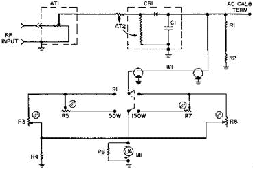
Figure 3-14 shows a common output power meter used in vhf-uhf applications. It has a 0- to 150- watt range covered in two steps: 0-50 watts and 0-150 watts. Attenuator AT1 provides a 50-ohm nominal resistive (dummy) load and uses metal film on glass construction. This dummy load is tapped to provide the proper operating voltage to the meter. Resistors R3 and R5 form a calibration network at 50 watts; R7 and R8 form a calibration network at 150 watts. Accuracy, at approximately 20º C, is ±5% for frequencies between 30 MHz and 600 MHz, ±10% for frequencies between 0.6 GHz and 0.8 GHz, and ±20% for frequencies between 0.8 and 1.0 GHz. When radio-frequency (RF) power is applied to AT1, this attenuator minimizes the effects of power factors generated by any reactive components. The RF energy is then detected and filtered by CR1 and C1, respectively. The resultant dc voltage, which is proportional to the input power, is applied to a sensitive microammeter via one of the calibration networks. This meter has a scale provided with two ranges: 0-50 watts and 0-150 watts. To protect the meter, you should always try the higher range first. If the value proves to be under 50 watts, a shift to the lower scale would provide improved accuracy.
3-16
Figure 3-14. - Vhf-uhf wattmeter.
In-Line Wattmeters
The AN/URM-120 in-line wattmeter, shown in figure 3-15, measures power applied to a 50-ohm impedance load and the power reflected from that load. The internal directional coupler is oriented such that it responds only to a wave traveling in one direction on the transmission line. The coupler can be rotated to accommodate either incidental or reflected power. The RF is then rectified, filtered, and applied to the meter, which is scaled in watts. The RF power of 50 to 1,000 watts can be measured between the frequencies of 2 MHz to 30 MHz; and 10 to 500 watts, between the frequencies of 30 MHz to 1,000 MHz.
Figure 3-15. - Typical in-line wattmeter.
3-17 Q-13. What is the advantage of using in-line wattmeters over output power meters?
Bolometer
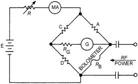
A bolometer features a specially constructed element of temperature-sensitive material. The active material is a semiconductor bead supported between two pigtail leads. When RF power is applied to a bolometer element, the power absorption by the element heats the element and causes a change in its electrical resistance. Thus, a bolometer can be used in a bridge circuit so that small resistance changes can be easily detected and power measurement can be accomplished by the substitution method (that is, substitution of dc or low-frequency power to produce an equivalent heating effect). a D'Arsonval meter movement is usually employed as the null indicator.
According to one principle of measurement (the principle used in the balanced bridge), the bridge is initially balanced with low-frequency bias power. RF power is then applied to the bolometer and the bias power is gradually removed until the bridge is again balanced. The actual RF power is then equal to the bias power removed.
According to another principle of measurement (the principle used in the unbalanced bridge), the bridge is not rebalanced after the RF power is applied. Rather, the indicator reading is converted directly into power by calibration previously performed.
Figure 3-16 illustrates the basic bolometer bridge circuit. The bolometer element must be physically small to be highly sensitive; it must be equally responsive to low-frequency and RF power; and it must be matched to the RF-input power line. The cross-sectional dimension of the bolometer element is approximately equal to the skin depth of RF current penetration at the highest frequency of operation. This condition permits the dc and RF resistivities to be essentially equal with the reactive component of the bolometer impedance at a minimum. Thermistors, which are a type of bolometer, use semiconductor material shaped like a bead, with a thicker skin depth and shorter length to minimize standing-wave effects. These physical properties assure correspondence between lengthwise low-frequency and RF power distribution to provide the necessary inherent accuracy of the bolometer.
Figure 3-16. - Basic bolometer bridge circuit.
An air-mounted bolometer provides a power sensitivity 100 or more times greater than that provided by static calorimetric devices. Additional sensitivity may be obtained by mounting the element within an evacuated envelope to eliminate convective heat loss. The small size of bolometer elements is associated with small thermal mass and short thermal time constants. The thermal time constant varies directly with the volume-to-area ratio of the element for a particular shape and composition. Typical time is up to 0.1
3-18 second for thermistor beads. The thermistor type of bolometer element is usually composed of a ceramic- like mixture of metallic oxides having a large negative temperature coefficient of resistance. Two fine platinum-alloy wires are embedded in the bead, after which the bead is heated and coated with a glass film. Typical dimensions of a thermistor bead used for microwave measurements are 0.015 inch along its major axis and 0.010 inch along its minor axis. The thermistor bead may be operated at high temperatures; it is rugged, both electrically and mechanically; it has high resistance-power sensitivity; and it has a good temperature-power sensitivity. In addition, it can endure large pulse energies; it has a sluggish thermal response; and it has negligible pulsed-power measurement errors. The more sensitive thermistor requires thermal shielding or heat compensation for best operation.
Q-14. What type of material is used in the construction of bolometers and thermistors?
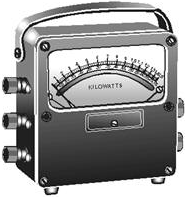
Bolometer Power Meter
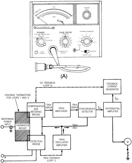
The standard power meter used in the Navy (Hewlett-Packard 431 C) is an automatic self-balancing instrument employing dual-bridge circuits. It is designed to operate with temperature-compensated thermistor mounts that enable you to measure power in a 50-ohm coaxial system from 10 MHz to 18 GHz and in a waveguide system from 2.6 GHz to 40 GHz. This power meter can be operated from either an ac or a dc primary power source. The ac source can be either 115 or 230 volts at 50 to 400 hertz. The dc source is a 24-volt rechargeable battery. a seven-position range switch allows full-scale power measurements of 10 microwatts to 10 milliwatts or of -20 dBm to +10 dBm. These ranges can be further extended with the aid of attenuators. The thermistor mount (as shown in fig. 3-17) contains two thermistors: one in the detection bridge, which absorbs the microwave power to be measured, and the other in the compensation and metering bridge, which supplies temperature compensation and converts the measured RF power to a meter indication. Each bridge includes its respective thermistor element as a bridge arm.
3-19
Figure 3-17. - Power meter.
Basically, the power meter circuit consists of two bridges; each bridge includes one of the thermistor elements as a bridge arm. The bridges are made self-balancing through the use of feedback loops. Positive or regenerative feedback is used in feedback loop 1; degenerative (negative) feedback is used in feedback
3-20
|
||||||||||||||||||||||||||||||||||||||||||||||||||