Module 21 - Test Methods and Practices |
||||||||||||||||||||||||||||||||||||||||||||||||||
|
Module 21 − Test Methods and Practices
Pages i , 1−1, 1−11, 1−21, 2−1, 2−11, 2−21, 2−31, 2−41, 3−1, 3−11, 3−21, 3−31, 4−1, 4−11, 5−1, 5−11, 5−21, 5−31, AI−1 to AI−3, Index
Testing Components by Comparison
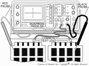
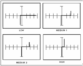
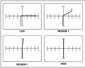
Testing components by comparison is the most preferred method for troubleshooting. The ALT (alternate) mode setup is the most commonly used mode for this method. This mode allows the technician to compare a known good component to a suspect component. This is accomplished by connecting channel a to a known good device, channel B to the device under test, and a common test lead to COM as illustrated in figure 2-34. Select the ALT button, and the 2000 will alternately display the signature of the known good device and the device under test. By examining the signature differences, you can detect a defective component. Figure 2-35 is a typical example of the CRT display on the 2000 while testing the base to emitter on a good transistor. Figure 2-36 illustrates a defective transistor under the same test setup. Note that in the low range, the transistor appears to be good. Sometimes component defects are more obvious in one range than another, so is a suspect device appears normal for one range, try the other ranges.
Figure 2-34. - Alternate mode setup.
2-41
Figure 2-35. - Signatures between base-emitter of a good transistor.
Figure 2-36. - Signatures between base-emitter of a defective transistor.
Q-31. What is the most preferred method of troubleshooting?
Q-32. Why is it recommended to use more than one range while troubleshooting a device?
Troubleshooting Tips
When you are testing individual components in a circuit, a parallel resistor or diode of similar value may cause a defective component to appear good. Therefore, you should, in most cases, electrically isolate the suspected component from the circuit while testing individual components. The best way to do this is to desolder all but one lead on the suspected component.
2-42 Q-33. When you are testing individual components in a circuit, what may cause a defective component to appear good?
You should be aware that devices made by different manufacturers may appear to have slightly different signatures. This is normal, especially with digital integrated circuits, and does not necessarily indicate a failed device. When this occurs, the best way to verify this is to compare the outputs of the device under test with the equipment specifications to ensure the signals are adequate for proper equipment operation.
Summary
The information that follows summarizes the important points of this chapter.
ELECTRON TUBES are usually tested for ShortS, TRANSCONDUCTANCE, and the presence of GAS. Several different types of tubes (i.e., TWTs, magnetrons, and klystrons) are normally tested in-circuit.
Most TransistorS can be tested by measuring the forward-to-back resistance of their junctions using a standard ohmmeter. The resistance scale of the ohmmeter must be carefully selected to ensure that the current rating of the transistor is not exceeded.
ESD-SENSITIVE DEVICES are components that require special handling. Some of the more sensitive devices can be damaged by static charges as small as 35 volts.
2-43
Most DIODES and MOSFETs can be tested by measuring the forward-to-back resistance of their junctions using a standard ohmmeter. MOSFETS, however, are classed as ESD-sensitive devices; and care should be exercised when handling or testing them.
INTEGRATED Circuits (ICs) have revolutionized the electronics industry. They are rugged, compact, and inexpensive. There is a wide assortment of equipment on the market designed for testing ICs.
BATTERIES are common to a large number of both electronic test equipment and operational equipment. You should be familiar with the different types of batteries, their test requirements, and the safety precautions to be followed.
RF ATTENUATORS and RESIsTIVE Loads are common devices that are widely used for attenuating RF signals and impedance matching. Resistive loads can be tested with a standard ohmmeter, and RF attenuators are normally tested through the RF substitution method.
2-44
Fiber-OPTIC CABLES are used primarily for the transmission of high-speed data over short distances. Their construction and theory of operation require that they be tested with a light source, usually a laser beam. There is a wide assortment of test equipment designed specifically for testing fiber- optic cables.
AUTOMATIC Test Equipment (ATE) is test equipment designed to evaluate the operational performance of a piece of equipment or printed circuit board (PCB).
2-45 The HUNTRON TRACKER 2000 is a versatile troubleshooting tool commonly used for statically testing resistors, capacitors, inductors, diodes, transistors, multiple-component circuits, and integrated circuits.
REFERENCES
EIMB, Test Methods and Practices, NAVSEA 0967-LP-000-0130, Naval Sea Systems Command, Washington, D.C., 1980.
Fiber Optic Communication Cables and Connectors, (Navy) EE169-CA-GYD-010/E110 TSER E & I, (Published under the authority of the Secretaries of the Air Force, Army, and Navy), 1983.
Fire Control Technician G 3 & 2, NAVEDTRA 10207-B, Naval Education and Training Professional Development and Technology Center, Pensacola, Fla., 1981.
Huntron Tracker 2000 Operation and Maintenance Manual, P/N 21-1052, Huntron Instruments, Inc., 15720 Mill Creek Blvd., Mill Creek, WA 98012.
Introduction to Microelectronics, NAVEDTRA 172-14-00-84, Naval Education and Training Professional Development and Technology Center, Pensacola, Fla., 1984.
Logic Clip 548A, NAVAIR 16-45-3102, Naval Air Systems Command, Washington, D.C., 1979.
Logic Comparator 10529A, NAVAIR 16-45-3100, Naval Air Systems Command, Washington, D.C., 1979.
Logic Probe 545A, NAVAIR 16-45-3105, Naval Air Systems Command, Washington, D.C., 1979.
Logic Pulser 546A, NAVAIR 16-45-3104, Naval Air Systems Command, Washington, D.C., 1979.
2-46
Answers to Questions Q1. Through Q33.
A-1. Lack of adequate storage space.
A-2. Open filaments.
A-3. Testing the tube in its circuit.
A-4. In their circuit.
A-5. Restore it to serviceable condition by operating it temporarily at reduced beam voltage.
A-6. Correct gain figure.
A-7. Rugged design.
A-8. Sensitive to heat and minor overloads.
A-9. Any range setting that produces a current flow through the transistor that exceeds 1 milliamp (usually R x 1 range).
A-10. 3,500 to 4,000 volts.
A-11. 35 volts.
A-12. For your own safety.
A-13. Voltages and resistances.
A-14. Greater than 10 to 1.
A-15. Gate and anode.
A-16. Current is allowed to flow in either direction.
A-17. Solder suckers create an electrostatic charge capable of damaging a MOSFET.
A-18. Low power consumption, compact size, and lower cost.
A-19. ICs cannot be repaired. All you need to test is output versus input.
A-20. a "1" or "0."
A-21. a "1" state.
A-22. a difference in logic states between the reference IC and the IC under test.
A-23. They provide you with a visual indication of the logic state at any point you choose in the circuit.
A-24. 10 feet.
A-25. a battery test set will test batteries under load conditions.
A-26. At 1.1 volts.
2-47 A-27. RF substitution method.
A-28. Reading their resistances with a standard ohmmeter.
A-29. High attenuation.
A-30. It eliminates the need for multiple pieces of test equipment and it is lightweight and portable.
A-31. Testing components by comparison.
A-32. Some defective devices may appear to be good in certain ranges.
A-33. a parallel resistor or diode of similar value.
2-48
|
||||||||||||||||||||||||||||||||||||||||||||||||||
