|
August 1962 Electronics World
 Table of Contents
Wax nostalgic about and learn from the history of early electronics. See articles
from
Electronics World, published May 1959
- December 1971. All copyrights hereby acknowledged.
|
This is probably the handiest
set of coil winding nomographs I have seen. Created by Donald Moffat, they appeared
in the August 1962 issue of Electronics-World magazine. Sure, a calculator
app might get the job done more quickly and to a greater number of decimal places,
but the beauty of using the graphical approach is being able to get a mental picture
of where all the numbers are in relation to each other. Besides, calculating a coil
value to more than a couple significant digits is an exercise in vanity unless you
are using a EM simulator where you are also defining dozens of physical parameters
for the conductor, insulation, nearby structures, temperature, etc. The author explains
how to use the dimensions of a coil to predict its inductance, distributed capacitance,
and self-resonant frequency. With nomograms "calculations" are performed simply
by drawing straight lines across the scales. Along with parameters like wire size,
coil diameter and length, number of turns, and spacing (turns/inch), it also
includes various types of insulation.
Coil-Winding Charts
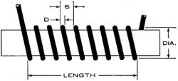
Fig. 1 - Basic coil geometry used in charts.
By Donald W. Moffat
Inductance is only one of the characteristics that determines a coil's suitability
in a specific application. Distributed capacity is equally important because it,
along with inductance, determines self-resonant frequency of the coil, the point
at which the coil becomes useless as an inductor. In fact, above its self-resonant
frequency, any coil will act for all the world as if it were a poor capacitor, except
that it will not block direct current.
This article will explain how to use the dimensions of a coil to predict its
inductance, distributed capacity, and self-resonant frequency. Nomograms are included
so that all "calculations" are performed simply by drawing straight lines across
the scales.
Inductance
Inductance is the property for which coils are used in circuits, and distributed
capacity is another property we must take into account in order to know the useful
inductance available. Roughly speaking, inductance can be increased by increasing
either the diameter of a coil or its number of turns.
Increasing the number of turns is more effective because inductance increases
as the square of the number of turns. In other words, doubling the number of turns
will increase the inductance by a factor of four, tripling the number of turns will
increase the inductance by a factor of nine. and so on. However, many of the changes
made to increase inductance will also increase distributed capacity, and the over-all
effect is to reduce the self-resonant frequency at a rapid rate. We can consider
a practical coil as consisting of an ideal coil (pure inductance, and no capacity)
in parallel with an ideal capacitor, and therefore increasing either one will reduce
the resonant frequency according to f = 1/ (2π√LC).
It is desirable, then, to have independent control over both inductance and distributed
capacity. To a certain extent, such control is available to those who wind coils,
through manipulation of the coil's silhouette. A series of 20-microhenry coils can
be made, ranging from long and thin ones to short and fat ones. Although each coil
has the same inductance, the different silhouettes will dictate that they have different
values of distributed capacity and therefore different values of self-resonant frequency.
Distributed Capacity
Dependence of distributed capacity on coil dimensions is not as straight-forward
as inductance is, but there are a few general rules to serve as guides. Coils that
range from short (those whose diameter is greater than the length) to medium (those
whose length is two or three times the diameter) will just about double their distributed
capacity when the diameter is doubled. In longer coils, up to those whose length
is 50 times the diameter, there is very little dependence on diameter. Beyond that,
we have the very long coils, where there is a definite reduction in distributed
capacity as the diameter is increased.
The length of a coil has an effect on its value of distributed capacity, but
the number of turns within a certain length has very little effect. For instance,
a coil one-inch long could be wound with 24 turns of No, 18 wire, or it could be
wound with 92 turns of No, 30 wire, but the distributed capacity will be about the
same in both cases. This is a means of exercising separate control over inductance
and capacity because you can take an existing coil design and switch to a finer
size wire. This will allow you to put more turns in the same length, having little
effect on distributed capacity but increasing inductance by the square of the added
turns.
These statements will prove helpful as long as you realize that they apply only
in a very general way and are on the lookout for exceptions. The nomograms will
give numerical answers which are adjusted to take care of exceptions to these generalities.
Usually, the goal is to wind a coil with as little distributed capacity as possible.
Even when a fair amount of capacity is acceptable, it should be controlled and its
value known so that the coil will be compatible with the rest of the circuit. If
minimum distributed capacity is the goal, the ideal coil is fatter than it is long,
having a diameter about one and a quarter times its length. Unfortunately, this
is not the most convenient shape to fit into an electronic chassis and it may be
necessary to accept more than the minimum amount of capacity and arrive at a compromise
coil shape. One advantage to the nomograms is that they make it easy to investigate
various possibilities, as will be explained shortly.
Coil Resistance
Every coil must have some resistance, which will determine the "Q" factor. However,
this factor determines just the sharpness of resonance and has very little bearing
on the actual frequency of resonance. Since this article is restricted to an investigation
of the interaction between inductance and distributed capacity, it will be assumed
that the results are independent of coil resistance.
Computations
One of the most important factors in single-layer coils is the length-to-diameter
ratio, which is used in the computations to follow. This ratio is found on Nomogram
1 and then is used as the first entry on the other two nomograms.
After the following instructions for using the nomograms, a simple numerical
example will be presented.

Nomogram 1 - Chart used to find the length-to-diameter ratio
and the distributed capacity of the air-core coils.
Distributed Capacity: Nomogram 1 is used for finding
both the length-to-diameter ratio and the distributed capacity.
There are two sets of numbers along the first scale. Turns per inch, on the right-hand
side of the scale is the basic number that is used for computations, and can always
be used. The left-hand side of the scale, wire gauge, is for convenience in the
unique but common case where single enamel wire is used and there is no spacing
between turns. For any other situation, the graph, along with Fig. 2, can be
used to arrive at a value of turns per inch. If the windings are closely spaced,
follow the line for the type of insulation out to where it crosses the line for
wire gauge and at that crossing note the number of turns per inch. For instance,
the line for No. 36 wire crosses the line for single silk insulation at 150 turns
per inch. If the turns are not wound as close as possible, but have some space between
them, determine the values of D and S (see Fig. 1) and then on Fig. 2 follow that
line out until it crosses the line for wire gauge, at which point you will read
the turns per inch. Remember that S in the figure includes the insulation over the
wire, a quantity that becomes increasingly important for fine wires.
Once turns per inch is determined, locate that value on the first scale of Nomogram
1, and the total number of turns on the second scale. Draw a straight line through
these two points and extend it to cross the third scale, where you will read the
length of winding. The actual value at this crossing is not important, as it is
only the point of crossing that is going to be used for drawing the next line. On
the other hand, if you knew the length of the coil, it would not be necessary to
perform this first computation; simply locate that value on the length scale, and
you are ready for the next step.
Next, locate the correct value on the diameter scale, and draw a straight line
from that point to the indicated point on the length scale. Where that line crosses
the middle scale, read a value of length/diameter, a value that will be used for
each of the other computations. As with the length of the coil, this step does not
have to be performed if the value is known, or if its computation can be done mentally.
For instance, if your coil has a half-inch diameter and is one inch long, it is
not necessary to draw the lines to determine that the ratio length/diameter is two.
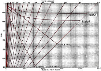
Fig. 2 - The number of turns per inch for wire having various
types of insulation.
The last step in determining distributed capacity starts with locating, on the
next to the last scale, the value which was found for length/diameter. Diameter
has already been located on its scale. Draw a straight line through these two points
and extend the line to cross the last scale. Now read the appropriate value of distributed
capacity.
Notice the peculiar layout of the sixth scale, to which the value of length/diameter
was transferred. Numbers go down from 50 to about 1 and then the rest of the scale,
down to 0.1, is folded back on itself, so that some spots on the scale are used
as the location of two numbers. Another point of interest is that numbers at the
lower end of the scale are quite crowded together, meaning that any ratios in this
range will give about the same amount of distributed capacity. Almost no accuracy
would be lost by saying that any value of length/diameter between 1.2 and 0.6 is
to be transferred to a location "near" the lower end of the scale.
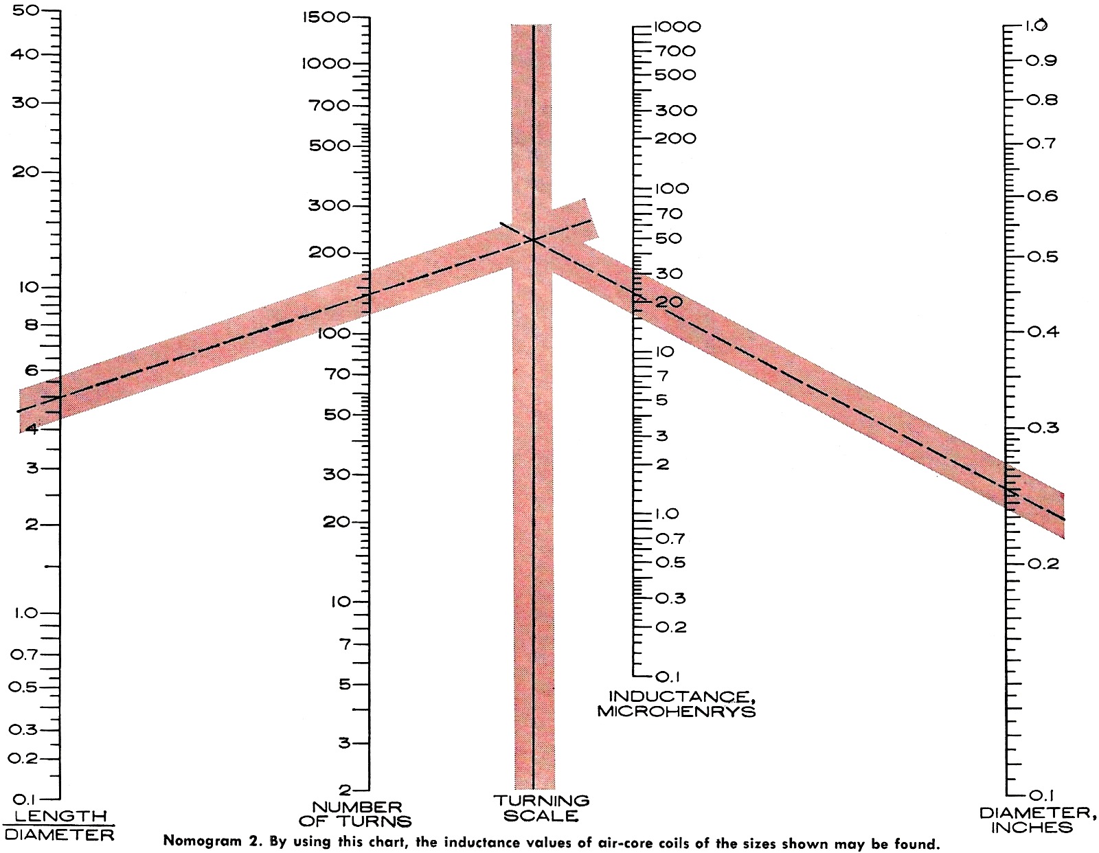
Inductance: Once length/diameter has been determined
from Nomogram 1, locate that value on the first scale of Nomogram 2, and locate
number of turns on the second scale. Draw a straight line through these two points,
extending it to cross the third scale. On the last scale, locate the correct value
of the diameter. Then a straight line drawn from that point to the point where the
first line crossed the turning scale will cross the fourth scale at the inductance
of the coil.
One of the advantages to the use of nomograms can be illustrated at this time.
If the inductance that is found is not the desired value, you can rotate a straight-edge
about the crossing on the turning scale until it passes through the desired inductance.
The straight-edge will then cross the diameter scale at the diameter necessary to
give that inductance. You can then work the first nomogram backwards to find a new
length of winding, and the coil is redesigned for the required inductance.
Self-resonant Frequency : Once length/ diameter has been determined from Nomogram
1, locate that value on the first scale of Nomogram 3, and locate the diameter on
the second scale. Draw a straight line through these two points, extending it to
cross the third scale. On the fourth scale, locate the correct number of turns,
and draw a straight line through that point and the point where the first line crossed
the turning scale. Extend that line to the last scale, where it will cross the self-resonant
frequency for that coil.
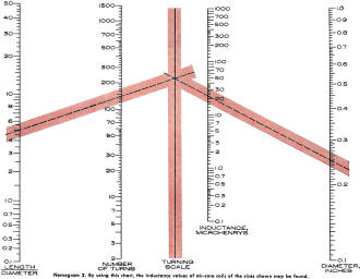
Nomogram 2 - By using this chart, the inductance values of air-core
coils of the sizes shown may be found.
Any coil is normally designed to operate at frequencies below self-resonance,
where it has a useful inductance. At frequencies above self-resonance, nothing can
be added to make the circuit resonate.
As with any other nomogram, it is easy to rotate a straight-edge about any point
to see the effects of changing one or more of the numbers.
Example
In order to be certain the instructions are clear, let's run through it again,
with numbers. Suppose you have 140 turns of No. 32 enameled wire on a quarter-inch
form. On Nomogram 1, locate 32 on the right-hand side of the first scale and 140
on the second scale. A straight line through these two points will cross the third
scale at 1.25, the length of winding. Next, locate 0.25 (quarter inch) on the diameter
scale and draw a line from that point to 1.25 on the length scale. It was not necessary
to note that the length was 1.25 because that value is not used in any of the other
computations and only the location of the crossing on that scale is important to
further computations. A straight line drawn through these two points shows that
the length/diameter ratio is 5. Locate 5 on the next to last scale and draw a line
from 0.25 on the diameter scale, through 5 just located, and this line will cross
the distributed capacity scale at 0.51 μμf.
Now, use Nomogram 2 to find the inductance. From 5 on its length/diameter scale,
to 140 on its number of turns scale, draw a straight line and extend it to cross
the turning scale. Draw another line from that crossing to 0.25 on the diameter
scale and the answer of 22 microhenrys is found on the inductance scale.
Self-resonant frequency is found on Nomogram 3. Draw a straight line from 5 on
the length/diameter scale to 0.25 on the diameter scale and extend it to cross the
turning) scale. From that point of crossing on the turning scale, draw a line through
140 on the number of turns scale and extend it to cross the last scale. At that
last crossing, read a self-resonant frequency of 48 megacycles.
Accuracy
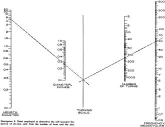
Nomogram 3 - Chart employed to determine the self-resonant frequency
of air-core coils from the number of turns and the size.
Several equations have been developed for computing the characteristics of a
coil. Unfortunately, we do not have universal agreement on a single correct set
of equations, each one seeming superior for different purposes. These nomograms
have been based on equations that have been supported experimentally over the ranges
of values used for the scales.
Coil leads, even though only a piece of straight wire, have both inductance and
capacity that add to those of the coil proper. In fact, a straight piece of wire
has a self-resonant frequency. For these nomograms, it has been assumed that there
are no leads on the coil, an assumption that introduces negligible error until the
coil is operating at frequencies of hundreds of megacycles and above. You can generally
figure that the calculated value of self-resonant frequency is the maximum possible,
and in the actual circuit, the coil will resonate at some lower frequency; some
safety margin should always be allowed.
Usually, the number of turns cannot be determined precisely because the last
turn does not have a definite ending, but tapers away from the rest of the winding.
At least some part of the last turn (and of the first turn) is more of a lead than
a part of the coil proper. Sometimes the last turn is wrapped around a terminal
or a pigtail and soldered in place. Any wraps not shorted by solder will form another
little coil, the characteristics of which will add to those of the main coil.
Weather conditions, such as temperature and humidity can have a noticeable effect
on the characteristics of a coil, especially if sufficient and constant tension
was not maintained during the winding.
Although the example used a quarter-inch coil form and we used 0.25 on the diameter
scale, diameter is really meant to be taken to the center of the wire. For fine
wire, the difference between the diameter of the coil form and the diameter to the
center of the wire is too small to have any bearing on the answer. However, when
using heavy wire on a coil form of small diameter, the accuracy can be improved
by adding the diameter of the wire to the diameter of the coil form.
The nomograms have been based on air-core coils because the use of other material
introduces several other variable conditions. Modifying the charts just to provide
for the effects of slugs would complicate them to the point where their usefulness
would be questionable. With air-core coils, however, considerable time and effort
can be saved by using the charts.
Nomograms for determining the inductance, distributed capacitance, and the self-resonant
frequency of coils.
Posted June 8, 2021
Nomographs / Nomograms Available on RF Cafe:
-
Parallel Series Resistance Calculator -
Transformer Turns Ratio Nomogram -
Symmetrical T and H Attenuator Nomograph -
Amplifier Gain Nomograph -
Decibel
Nomograph -
Voltage and Power Level Nomograph -
Nomograph Construction -
Nomogram Construction for Charts with Complicating Factors or Constants
-
Link Coupling Nomogram -
Multi-Layer Coil Nomograph
-
Delay Line Nomogram -
Voltage, Current, Resistance, and Power Nomograph -
Resistor Selection Nomogram -
Resistance and Capacitance Nomograph -
Capacitance Nomograph -
Earth
Curvature Nomograph -
Coil Winding Nomogram -
RC Time-Constant Nomogram -
Coil Design
Nomograph -
Voltage, Power, and Decibel Nomograph -
Coil Inductance Nomograph -
Antenna Gain Nomograph
-
Resistance and Reactance Nomograph -
Frequency / Reactance Nomograph
|