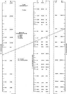
RC Time-Constant Nomogram
|
|
After learning Ohm's law, Kirchhoff's law, Norton's theorem, and a few mesh analysis techniques for resistive circuits, electronics students' first foray into the interactions of resistors, capacitors, and inductors is usually time constants. The so-named "RC time constant" is simply multiplication of the values of resistance (ohms) and capacitance (farads) - connected in series - resulting in a time value in seconds. There is nothing special about the time constant other than various rules of thumb which have been designed around it. For instance, 5 RC time constants is considered the time after which a fully discharged capacitor is charged (up to 93.3%, actually), or conversely the time after which a fully charge capacitor is discharged (down to 6.7%). It does so happen that after 1 RC time constant the charge has changed by a factor of 1-e-1 (1-0.368=63.2%). After 5 RC time constants the charge has changed by 1-e-5 = 99.3%. 6 RC time constants yields 99.8%, 7 is 99.9%. 9 RC times constants results in 99.99%. Although not mentioned here, there also the "RL time constant" for series resistor and inductor configurations, where T = L/R. RC Time-Constant Nomogram
Chart permits quick method of finding combinations of resistance and capacitance to produce the required time-constant combination. The purpose of this nomogram is to simplify the calculations of RC time constants. Although the operation is fairly simple it can become cumbersome with powers of 10. More useful, however, is the ability - with this nomogram - to find combinations of Rand C which will give the desired time constant. Various scales are given so that wide ranges of T, R, and C can be found without any calculations. The various possible scale combinations are shown on the nomogram. Example: Find the time constant of an RC network which has a 1.5-megohm resistor and a 40-pf. capacitor. Solution: Using the AEG scale combination, draw a straight line from 1.5 on the A scale to 40 on the G scale. The answer, 60 microseconds, is found on the E scale where the drawn line crosses the time scale.
Posted August 25, 2022 Nomographs / Nomograms Available on RF Cafe: - Parallel Series Resistance Calculator - Transformer Turns Ratio Nomogram - Symmetrical T and H Attenuator Nomograph - Voltage and Power Level Nomograph - Nomogram Construction for Charts with Complicating Factors or Constants - Voltage, Current, Resistance, and Power Nomograph - Resistance and Capacitance Nomograph - Voltage, Power, and Decibel Nomograph |
|

