Delay-Line Nomograms
|
|
Delay lines are used in electronic circuits for precisely adjusting the timing of signals. That can be to set times between events or to adjust two or more signals so that they arrive at some point in the circuit at a specific time with respect to each other. In a radar system, for instance, a sample of the reflected signal might be delayed in time by one pulse repetition period in order to compare it to the current reflected signal so that stationary (fixed, non-changing) signals can be cancelled out, leaving only the signal that has changed since the last sample. That is how MTI (moving target indication) functions. In today's world the samples are stored digitally and then compared digitally with other signals, but previously in fully analog systems, sending the sample along a longer (in time) path for comparison was necessary. Delay lines can be electrical like the ones covered in this 1962 issue of Electronics World magazine, or they can be mechanical such as with a quartz or mercury delay line. The provided nomographs are for LC (inductor-capacitor) delay lines. Delay-Line Nomograms
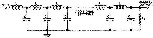
Fig. 1 - Basic circuit arrangement of a multi-section LC delay line. By Donald W. Moffat Useful graphical information to speed the design of LC delay lines with various delays and rise times. Delay lines are finding many applications in electronic equipment because they are passive timing devices capable of extremely good accuracy under severe environmental conditions. Many of these lines can be made in any laboratory and the accompanying nomograms will enable the reader to design a delay line quickly for the desired characteristics.
Fig. 2 - Nomogram for determining the number of sections needed.
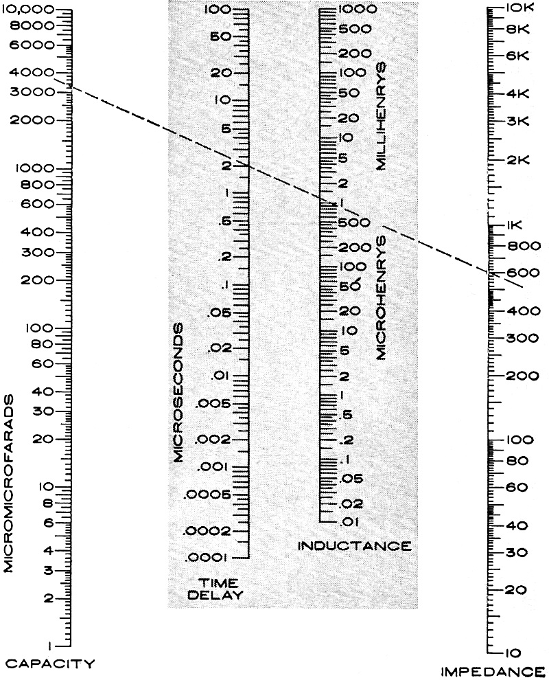
Fig. 3 - Nomogram used to obtain total inductance and capacity. Two broad classes of delay lines are the mechanical and the electromagnetic. The first group is characterized by long delays, up to thousands of microseconds, and large attenuation. They are made of special and expensive equipment and are not ordinarily within the province of anyone but the specialist in their manufacture. On the other hand, electromagnetic delay lines consist of a network of coils and capacitors, as shown in Fig. 1, and experimental models can be constructed at any electronic workbench. The length of time by which such a line delays the signal is a function of just the total inductance and capacity, in accordance with the formula: T = √LC, which uses the basic units of seconds, henrys, and farads. If inductance and capacity are expressed in microhenrys and microfarads, respectively, then time will be calculated in microseconds. This equation shows that time delay can be increased by increasing either capacity or inductance or both. However, if the characteristic impedance of the line is to be considered, the ratio of L to C must be watched. Characteristic impedance of a line is the impedance which the line presents to the circuit that feeds it. For instance, if the signal from a source with 2000-ohm internal impedance drops to half its open-circuit value when a delay line is connected across it, then the delay line also has an impedance of 2000 ohms. When the delayed signal reaches the end of the delay line, some of it will be reflected back unless the line is terminated in a resistance equal to its characteristic impedance. In general, proper matching will produce the best waveform and the maximum signal output. The formula for characteristic impedance is: Z0 = √LC, where Z0 is in ohms when both Land C have the same prefix, such as "micro." This equation shows that increasing inductance will increase impedance, increasing capacity will decrease impedance, and they can both be changed without affecting impedance if their ratio remains unchanged. In Fig. 1, the coils are in series and the capacitors are in parallel. Therefore, total values as given by both the formulas are found by adding up those of each section. Conversely, the values for one section are found by dividing the totals by the number of sections. The number of sections is selected on the basis of the desired quality factor, which is defined as total delay divided by output rise time. The higher this ratio, the better the delay line because either a long delay or a short rise time will increase the quality factor. In designing a delay line, the procedure is to select values of total inductance and capacitance, then divide those totals into the number of sections necessary to give the desired quality factor.· An Example This example will help explain the use of the nomograms. Suppose it is desired to have a total delay of 2 μsec., a rise time of 0.2 μsec., and a characteristic impedance of 600 ohms. First, we refer to the nomogram in Fig. 3. On Fig. 3, locate 2 μsec. on the "Time Delay" scale and 600 on the "Impedance" scale. Draw a straight line through these points and where that line crosses the other scales, it will give the required values of inductance and capacitance as 1.2 millihenrys and 3200 μf., respectively. Use Fig. 2 to determine the number of sections required. Locate 2 μsec, on the "Time Delay" scale, 0.2 μsec. on the "Rise Time" scale, and draw a straight line through these two points. At the middle scale the line indicates that 2.5 sections are required, therefore each coil should have an inductance of 48 micro-henrys and each capacitor should have a value of 128 (nearest standard value of 130) μμf. This basic section of 48 microhenrys and 130 μμf. can be used to make small corrections to the total delay. Each section contributes a delay of 1/25 of the total, or 0.08 μsec. and sections can be added without affecting the characteristic impedance of the line, because the ratio of L to C will remain unchanged as sections are added.
Posted October 13, 2022 Nomographs / Nomograms Available on RF Cafe: - Parallel Series Resistance Calculator - Transformer Turns Ratio Nomogram - Symmetrical T and H Attenuator Nomograph - Voltage and Power Level Nomograph - Nomogram Construction for Charts with Complicating Factors or Constants - Voltage, Current, Resistance, and Power Nomograph - Resistance and Capacitance Nomograph - Voltage, Power, and Decibel Nomograph |
|