I have mentioned this before, but nearly always the setting for John Frye's "Mac's
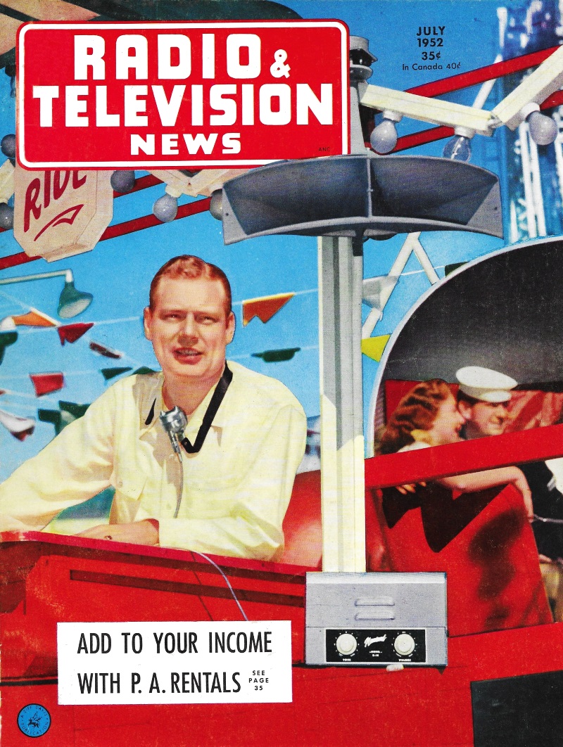
Service Shop" technodrama™ stories coincide with the time of year corresponding to
the month in which it appeared (for the northern hemisphere) - in this case the
July 1952 issue of Radio & Television News magazine. In addition to
that, Barney's crack about Mac using his slide rule to try calculating who the president
would be is also time-appropriate since 1952, being a Leap Year, was also an election
year (Eisenhower
beat Stevenson, BTW) ...but I digress. Mac's actual preoccupation was with open
wire transmission lines. With the rise of UHF broadcasting on the horizon, he predicted
that such lines would become popular due to their lower signal attenuation compared
to standard 300 Ω plastic-insulated twin lead. Open line (aka ladder
line or window line) at 500 MHz exhibits about a quarter the loss when dry
and as much a twentieth the loss when wet (depending on the quality of the standard
300 Ω twin lead). Mac provides a useful tutorial on why open wire line impedance
is set at 450 Ω rather than the traditional 300 Ω or some other value.
A Gonset ad for the "open wire line" mentioned in the article is shown tot he left.
Mac's Radio Service Shop: "Open Wire Lines"
 By John T. Frye By John T. Frye
The sticky, sultry heat took away a person's appetite, and Barney used only a
few minutes of his lunch hour to down a sandwich, a frosted malt, and a double-decker
ice cream cone; then he fortified himself with a giant lemon Coke "for the road"
and went back to the service shop. The inside of the shop felt cool and comfortable
after the glaring heat outside, he thought to himself, as he passed through the
empty front of the store to the service department at the rear.
Mac, his boss, looked up from where he squatted tailor-fashion on the service
bench in the direct path of a humming electric fan that rustled the litter of papers,
letters, magazines, and books about him. A slide rule was balanced on one knee,
and he was chewing reflectively on a stub of pencil.
"Well, this is a switch: getting back early!" he remarked to his red-headed assistant.
"You sick or something?"
"No," Barney replied as he collapsed on the other end of the bench. "I just love
my work. What are you doing? Trying to dope out who the president is going to be?"
"Not exactly. I'm boning up on open wire transmission lines."
"Why the sudden interest in that?"
"For one thing, you may have noticed that they are becoming increasingly popular;
but more important than that is my guess that they will get a lot more usage when
u.h.f. TV stations really get going."
"Why, Daddy?" Barney asked in a rasping falsetto.
"Because the losses of ordinary flat twin-lead go up rapidly as the frequency
increases. For example, at 500 megacycles, the dry-line loss is 3.2 db per hundred
feet, and the wet-line loss zooms up to 20 db per hundred feet. Opposed to this
is an open wire transmission line loss of only 0.78 db when dry and not much greater
than this when wet."
"How about tubular twin-lead?" "There is not too much difference in the dry-line
loss, but the wet-line loss of tubular twin-lead is only 6.8 db per hundred feet
at 500 megacycles. Even so, that is about eight times the loss of open wire line."
"Where are you getting all this information?"
"From a lot of sources: The good old 'The Radio Amateur's Handbook' has a lot
of good stuff on open wire lines; so does Terman in his 'Radio Engineering.' I also
went back through our magazine files and dug out all the articles on transmission
lines that were published in the past ten years. Still, though, there were a lot
of practical points I wanted to know about actually using the lines, and I decided
the best place to go for the answers was to the men who built them. Gonset was the
originator of the 450-ohm open wire line for TV use; so I wrote to them and got
a fine letter back from W. W. Smith, chief engineer of the company. Radio Merchandise
Sales, usually called 'RMS,' is another big outfit that makes this line and several
accessories for it; so I also wrote to them and received a prompt and detailed answer
from their chief engineer, Martin Bettan. Thanks to the courtesy and help of these
men and also to the books and magazine articles I have been reading, I am full up
to here on open wire transmission lines. Just try and stump me!"
"Okay, why did they make the lines 450 ohms? Why not make it 300 ohms so it would
match most existing antennas and receivers?"
"If the line were reduced to the spacing necessary for 300 ohms, the capacitive
losses would render it useless as low-loss lead. The only advantage it would then
have over ordinary twin-lead would be the difference in the dielectric losses, and
this would probably be offset by the effect of slight irregularities in spacing
that would cause more difficulty when the wires were closer together.
"The 'free space' line loss goes down with increasing impedance up to the point
where line radiation becomes appreciable; so it might seem that it would be a good
idea to make the impedance of the line much higher, say up to 1000 ohms. There are,
however, several good reasons for not doing this: first, the increased spacing would
make the line bulkier and harder to handle and support; secondly, the field about
a wider-spaced line would be more intense, and this would mean it would have to
be kept farther away from other objects if losses were to be avoided; thirdly, as
the spacing was increased, the tendency of the line to pick up noise would increase;
and finally, the one-inch spacing of 450-ohm line seems. to be a good compromise
because its impedance is so close to that of ordinary 300-ohm twin-lead that, in
most cases, the two can be used interchangeably."
"How about that? Can you just ignore the fact that you are using a 450-ohm line
to connect a 300-ohm antenna to a 300-ohm TV receiver?"
"In most cases, yes. After all, that is only a mismatch of 1 1/2:1, and a mismatch
of 2:1 can be withstood without serious defect. One thing you must keep in mind
is that the receiver and the antenna have a 'nominal' impedance of 300 ohms. Actually,
they may vary widely from this figure. If it happens that the receiver impedance
is substantially below 300 ohms, then the use of a 450-ohm line may result in a
noticeable loss of signal or even bad standing waves on the line."
"What do you do about that?" "Match the impedance of the line to the nominal
impedance of the receiver. If you are only interested in receiving one TV station
- and in many areas, that is all you can get - matching the impedances can be done
by means of a quarter-wave matching transformer. Such a transformer is just a length
of line that is a quarter wavelength long at the frequency being received and that
has the proper impedance to act as a transformer from the 450-ohm line to the 300-ohm
receiver."
"What would that proper impedance be?"
"The impedance of the quarter-wave section should be equal to the square root
of the product of the two impedances being matched. In this case that would be the
square root of 300 times 450 or, u-m-m-m-m -" he hesitated as he manipulated the
slide rule, "about 368 ohms. Since the impedance of an open line is simply a function
of the size of the conductors and the spacing between them, it is no big job to
make up such a transformer from the impedance charts given in any good handbook."
"What if you want to match the 450-ohm line to a 50- or 75-ohm input?"
"Those lower inputs are usually intended for coaxial lines; so the problem is
not just one of matching impedances, but you also have to convert from a balanced
to an unbalanced line at the same time. The device known as the 'balun' is the ticket
for that, and the March, 1952, issue of the technical section of 'Sylvania News'
contains complete constructional information on making such a gadget for matching
450-ohm line to either of those unbalanced impedances you mentioned," Mac said as
he slid a paper across to Barney.
The youth looked it over casually for a few seconds and then said:
"You say the quarter-wave transformer is all right for one frequency when going
from 450 to 300 ohms, but what if you want to receive several TV stations widely
separated in frequency?"
"Then a tapered-line transformer is the best answer. In fact, it is probably
the best answer in any case. Such a transformer is simply a section of transmission
line in which the spacing between the conductors changes in a linear fashion from
a spacing that would be right for the higher impedance down to a spacing that is
correct for the lower impedance. The 450-ohm line is connected to the wide end,
and the 300-ohm line or the receiver input is connected to the narrow end of the
tapered line. A wave traveling through this tapered section has its voltage-current
ratio gradually transformed in accordance with the change in characteristic impedance,
and so there are no reflected waves produced."
"How long does that tapered section have to be?"
"That depends upon the lowest frequency you want to receive. Terman says that
the tapered line will give almost perfect impedance transforming action from very
high frequencies down to a frequency at which the length of the tapered section
is about a wavelength. At lower frequencies, particularly when the tapered section
is less than a half wavelength, the tapered section becomes an abrupt change in
impedance and standing waves are set up. The exact point at which this unfavorable
condition becomes serious depends somewhat on the ratio of the impedances being
matched. At a 2:1 ratio, the critical length of the tapered section is between one-half
and a full wavelength. As the ratio becomes smaller, the tapered section can be
shorter without increasing the standing waves; and since we are matching impedances
with a ratio of 1 1/2:1, that is in our favor."
"Can you buy a tapered line transformer?"
"Yes. RMS, for one, makes such a transformer and recommends that it be tried
both at the antenna and receiver when installing 450-ohm line. When a noticeable
improvement results, it should be left in; but if no change can be seen, it can
be omitted."
"How about making your own?
Some of the guys have told me that they just split twin-lead for about a foot
and fan it out to meet the spacing of the 450-ohm line."
"From what I have just told you about the minimum length of the tapered section,
I doubt if that practice is a good one, especially for the low-frequency channels.
Gonset recommends that you remove five spacers from the end of their line by snipping
the spacers with diagonal cutters from the back parallel to the wires. Then cut
the wires to exactly thirty inches from the last spacer. Strip and splice to 300-ohm
ribbon, using solder or 'Stakon' solderless connectors. Keep the tapered section
taut by mounting in such a manner that tension is kept on this section and twisting
is prevented. They say this results in a very efficient tapered line impedance transformer."
"How do you support the 450-ohm lead-in ?"
"Use regular stand-offs where the line goes down the mast or the side of a building.
The spacer is slipped into the opening of the grommet intended for coax, and then
if necessary the ring is pinched tight with gas pliers. Care should be taken to
see that the ring is evenly spaced from each of the conductors. Where you have long
horizontal runs, say across a ravine or down the side of a hill, RMS makes and recommends
a spring-type stand-off for keeping an even tension on the unsupported span. Gonset
suggests that if spans of more than 150 feet (or 100 feet when icing or strong winds
are present) are used, the line be supported by a galvanized steel messenger wire,
with the line at least six inches below it. When you want to turn a corner, you
turn the line up on edge with a 90-degree twist and support it vertically at the
end.
"Keeping in mind that a higher impedance line has a larger field around it, at
least seven-inch stand-offs should always be used, and care should be taken to see
that the line stays well clear of gutters, downspouts, and other metallic objects."
"How do you get the line into the house ?"
"You could saw two ditches in the window frame, lay the wires in these, and then
fill the cuts with plastic wood; but a better system is to use a tapered line transformer
just at the point where the line is to enter the house and then come on in with
regular 300-ohm ribbon. Since the ribbon will be inside, out of the weather, any
lossses it adds will be negligible."
"What if the antenna is a rotating kind? You can't go wrapping that 450-ohm lead
around, can you?"
"No, but in a new installation you could use a motor of the sort that carries
the antenna connections through the rotating mechanism on slip rings. Otherwise,
the best thing to do would be to again use a tapered line transformer right at the
top of the tower and then go from that point on up to the antenna with a good quality
twin-lead that will withstand flexing. Since this twin-lead section will be short,
it will not add very much loss, even in foul weather."
"Do you twist the line coming down the tower?"
"Mr. Smith of Gonset says that from the standpoint of theory and actual tests,
there is no point in twisting the line to reduce noise pickup - something I've been
suspecting for quite a while. As a matter of fact, transposing any balanced line
precisely every half wavelength will actually increase the noise pickup broadside
to the line."
"How long a run do you think it takes to make using 450-ohm line worthwhile?"
"On the v.h.f. channels, and under conditions of dry weather, and considering
only the signal loss, it would probably not be worthwhile to use 450-ohn line for
a length less than 100 feet. But when you consider how sharply the loss of ribbon
line goes up when it gets wet, and when you consider the permanence of the open
wire line, it can easily be worth-while even on shorter lengths. This is especially
true where sea coast salt or industrial area soot quickly impairs the initial efficiency
of ribbon lines.
"And now that we have to start thinking about u.h.f. installations where transmission
line losses really become serious, I am confident installers are going to turn more
and more to the 450-ohm open wire line."
"it figures," Barney agreed as he smothered a prodigious yawn and slid from the
bench. "And on top of that Margie, my one-and-only, says she thinks they are cute
because they remind her of little ladders that the TV signals can use in climbing
down from the antenna!"
Posted October 28, 2021
Mac's Radio Service Shop Episodes on RF Cafe
This series of instructive
technodrama™ stories was the brainchild of none other than John T.
Frye, creator of the Carl and Jerry series that ran in
Popular Electronics for many years. "Mac's Radio Service Shop" began life
in April 1948 in Radio News
magazine (which later became Radio & Television News, then
Electronics
World), and changed its name to simply "Mac's Service Shop" until the final
episode was published in a 1977
Popular Electronics magazine. "Mac" is electronics repair shop owner Mac
McGregor, and Barney Jameson his his eager, if not somewhat naive, technician assistant.
"Lessons" are taught in story format with dialogs between Mac and Barney.
|