Mac's Service Shop: Zenith's 1973 Color Line
|
|
Those of us who have been around for six or more decades have lived through two evolutions of video display types - raster scanned cathode ray tubes (CRTs) and digitally pixelated light-emitting diode (LED) and liquid crystal (LCD) displays. Unlike with the latter display types that improved in color depth, picture resolution and display size, the former had effectively a fixed resolution of horizontal lines (525 vertical steps - only 484 visible, actually, due to blanking). That meant for CRTs, designers needed to find ways to make images appear in-focus while also looking continuous on larger screens. Doing so involved cleverly adjusting the size and spacing of fluorescent color dots on the picture tube face while also using special metal masks between the electron gun and the tube. A lot of research that included panels of people rendering opinions went into determining what would be considered an acceptable tradeoff in larger size vs. picture quality. Somehow, the higher quality 25" (some even up to 27") television set pictures looked pretty darn good if you didn't sit right up next to the screen. To get an idea of how profoundly minor changes in scan techniques can effect picture quality, open the Display Settings screen in the Control Panel and change the resolution to something other than the "native" resolution. Most likely you will get a picture that makes you think your eyes have gone out of focus, at least until you move far away from the screen. Mac's Service Shop: Zenith's 1973 Color Line
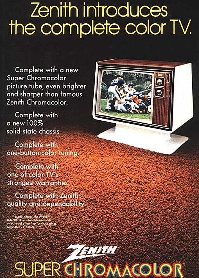
Lay down your solder gun. Barney," Mac said to his assistant. "I want to update you on the Zenith 1973 color TV line we're going to be encountering before long. I bought these service manuals from the company and have been studying them. Now I'm ready to bestow my acquired wisdom on lucky you." "No contest," Barney said. "I'd always rather listen than work. Blast off." 1973 Zenith 25" Super Chromacolor Console TV
Zenith Super Chromacolor Portable TV (1973 TV Guide Fall Preview issue) "First, Zenith has two complete color TV lines for 1973. Sets in one line are remote controlled; those in the other, manually controlled. If the customer goes for remote control he can have it in one 16" portable, or two 19", one 23" or one 25" table models. He can also get RC on ten 25" consoles or two 25" combinations. But he still must make up his mind how sophisticated a remote control he needs. The four-button 600-X turns the set on and off, switches vhf and uhf channels higher or lower, adjusts the volume to one of three levels, and mutes the sound. The three-button 500 system turns the set on and off, adjusts the volume to two levels or mutes the sound, and changes the vhf channels higher or lower. The 100 system turns the set on and off and changes vhf channels higher or lower with a single button. All three systems use Zenith's Space Command mechanically produced ultrasonic signal. "Twenty-six sets in the manually operated line break down into two 16" portables; five 19", one 23" and one 25" table models; four 23" and twelve 25" consoles; and one 25" combination. All Zenith color sets are served by three basic chassis. The Titan 200 is 100% solid-state and features the Zenith Dura-Module concept of five good-sized plug-in modules. Incidentally, transistors and IC's on these modules are also plug-in and can be replaced when necessary without changing the entire module. The Titan 101 chassis is over 90% solid-state and also uses Dura-Modules. The High Performance Chassis used in the portables features Zenith's solid-state 3-stage i-f module with an amplification factor of 26,000. This module has been modified this year by incorporating a hot-carrier diode for detection and changing the biasing for the third i-f transistor to increase reliability. "The sound module, employing an IC amplifier, has also been changed this year so the volume control varies a dc potential applied to the IC amplifier to control its gain instead of varying the audio signal directly. You'll also find a change in the black-and-white tracking adjustment procedure. Instead of using potentiometers to vary the red, green, and blue gains, Zenith does this with taps in the red and blue cathode circuits. Don't waist any time looking for knobs to twist. Just read the service procedure. "What's the 'Chromatic Brain' that I hear Zenith yakking about?" "That's their name for circuitry designed to detect and extract color information from the signal. It's built around a Zenith-developed IC containing two independent, double-balanced demodulator systems. But there's no point in our going into features you take for granted on a modern color set - such as automatic degaussing, afc, motor-driven touch tuning, etc. Instead I'd like to call your attention to such things as Zenith's solid-state electronic tuning, their voltage-regulating transformer, their chromatic one-button tuning, system and their Super Chromacolor picture tube. "The solid-state electronic tuning is standard in ten of the 25" color sets in the remote control line and provides for control of both the solid-state vhf and uhf tuners through a solid-state 'nerve center' mounted on its own Dura-Module. With this system, up to fourteen pre-tuned channels, locally available, can be set up through the front of the set in any combination or sequence desired for direct channel-to-channel tuning by the hand-held RC unit. When desired, new channels can be quickly added or substituted for one no longer watched, thus providing true 82-channel remote control." The Voltage-Regulating Transformer "The voltage-regulating transformer is used in their 25DC56 color TV chassis. (Incidentally, the '25' in the chassis number indicates a 25" diagonal picture tube; the 'D' indicates the year 1973; the 'C' stands for color, and the '56' is the individual chassis designation.) This transformer supplies all voltages required with reasonable regulation under power line variation from 95 V to 140 V. This is done by using a transformer with loose coupling between primary and secondary windings and by tuning the secondary winding to resonance at the 60-Hz line frequency by means of an externally mounted 3.5-μF oil-filled capacitor. Resonating the secondary causes the voltage to increase until the core material saturates, rendering any further increase in voltage impossible. The effect is much the same as if you had a double-ended zener across the secondary. Not only does this arrangement provide good regulation of the secondary voltage through wide swings of the line voltage or current demands, it also suppresses transient pulses on the incoming power line-transients that can wreck transistors and IC's. For example, the total B-plus change on the 128-V line is approximately only 5 V with brightness varied from minimum to maximum or with the line voltage changing from 100 V to 132 V; and a 30-V transient appearing in the primary for 2 seconds appears on the output side at less than 15 V in amplitude and lasts for only about 100 milliseconds. Still another advantage to the loose coupling of the transformer windings is the limiting of short-circuit currents. Under conditions of a direct short circuit across the secondary, the current will increase only to about double the normal current, which will trip the circuit breaker with no damage to the transformer. But let me warn you of one thing: don't expect to get the rated 6 volts rms on the filament of the picture tube if you use a conventional D'Arsonval meter movement where the rms voltage is derived from a sine wave peak detector. You're measuring a square wave produced by the limiting action of the transformer, and a true rms-reading meter or a dynamometer movement must be used. It would be a good idea if Zenith would provide a scope measurement of this filament voltage. Not many service technicians have dynamometers! One-Button Tuning "Zenith's chromatic one-button tuning system features versatility, and is available on thirty-eight sets, spread over both color lines. With the Chromatic Tuning button off, the color-level, tint, contrast, and brightness are adjusted with the manual controls to taste. When the button is on, it lights with an orange glow and a 'second' set of controls pre-set at the factory for a normal picture, are switched in and override the manual controls. "But the owner may prefer a different 'normal' picture than the factory set up. If so, with the Chromatic Tuning on, he or the service technician can readjust the brightness, contrast, color level, and tint with an insulated screwdriver provided. From then on, any time the Chromatic Tuning is on, the owner's custom-selected picture appears automatically on the screen. "Finally, even if he does not change the factory settings, he still has a short range of adjustment with the manual controls when the Chromatic Tuning is on. He can make slight changes in flesh tones and color intensity to compensate for discrepancies that may occur with older color movies, certain taped programs, and occasional variations in transmission by TV stations." Super Chromacolor Picture Tube® "That brings us to Zenith's 1973 Super Chromacolor Picture Tube. I'm always astonished that a Rube Goldberg contraption such as the three-gun shadow mask color picture tube - with all the precise geometry and nanosecond timing its operation demands - can be made to work at all; yet Zenith seems to have brought that performance closer to perfection by achieving a significant increase in brightness by increasing the area of total active phosphor on the face of the tube. "As you know, the shadow mask is used as a stencil in depositing the dots of the phosphors on the tube face. That means the size of the holes in the shadow mask - some 450,000 such holes in a 25" tube - determines the size of the phosphor dots. In a standard tube the dots are 17 thousandths of an inch in diameter at the center. The electron beam is 13 thousandths in diameter. Being smaller than the dot, the beam illuminates only 45% to 65% of each dot. The remaining dot-area is needed as a 'guard band' or tolerance allowance for the alignment of electron beams and phosphor dots. By allowing a larger target for the beam to hit, we avoid discoloration produced by slight beam misalignment. The aluminized area between dots in a standard tube reflects room light and causes washout and loss of picture contrast. To overcome this a low-light-transmission glass is used in the face of the standard tube to cut down on reflected light. Unfortunately it also absorbs about half of the actual screen brightness. "The original Chromacolor tube, patented in 1964 and introduced in 1969, doubled the brightness of the then-standard tube by illuminating each dot completely and surrounding the dots with a jet-black light-absorbing material that soaked up reflected room light. Tubes employing this black-surround feature are called 'matrix' tubes and are used by several manufacturers because they permit the use of higher light-transmission glass in the face of the tube and consequently brighter pictures without increasing room light reflection. "Zenith employs what they call the 'negative guard band' approach in which the electron beam is made larger than the phosphor dot, and it is done with their 'Iris Mask.' A mask is first prepared in normal fashion except the holes are smaller - 9 thousandths of an inch in diameter at the center in the original Chromacolor tube - and it is used in depositing the phosphor dots. Then the mask is removed and the holes are acid-etched to 14.5 thousandths at the center of the tube. Now we have a beam larger than the dot; so the entire surface of the dot and part of the black area surrounding it are illuminated. Even if the larger beam is slightly misaligned, it will still illuminate the entire dot, instead of the 45% to 65% formerly illuminated by the smaller beam. "There are other less important changes. In the original Chromacolor tube the dots grew progressively smaller moving from the center toward the edges. This provides additional guard band to assure alignment of the sharply-deflected beams at the edges. The decrease in size was in the form of concentric circles with the dots in each circle being the same size, but growing smaller as the circles grew larger. In the Super Chromacolor tube, the decrease in size is in the form of concentric rectangles instead of concentric circles. With this configuration, the majority of holes in the mask are larger than in the previous Chromacolor tube, although some at the edge are actually smaller. Finally, the electron guns are made more precise to approach the ideal of a perfectly round electron beam. A beam slightly oval in shape produces a tiny amount of distortion." "Zenith got a reputation of being kind of reaction my when they were so slow to switch over from hand-wiring to printed circuits," Bamey offered. "Probably conservative would be a better word," Mac suggested. "Maybe they follow Pope's advice: 'Be not the first by whom the new is tried, nor yet the last to lay the old aside.' Perhaps this comes from taking their advertising slogan seriously. 'The quality goes in before the name goes on.' Those first PC boards, with their plated-through holes and their flimsy construction, were pretty horrible. I know Zenith carries on an aggressive research program, and just last October they demonstrated a 0.63- inch thick TV display panel using a matrix, and gas discharge principle. Their Robert Adler forecasts we shall have flat wide screen TV by 1985 at the latest, and he says a component failure in any part of a TV receiver should be a rare event by that time. He also speaks of their experiments with 3-D holographic TV, although be is not optimistic about this being perfected in the near future. "Incidentally, their advanced color-TV research groups are housed in the new parts and service administrative headquarters at 5600 West Jarvis Avenue, Niles, Illinois. This is also the base for Zenith's customer relations service program in which P. J. Wood, Vice-President Customer Relations, says: 'Service is arranged for virtually 100 percent of all customer complaints as soon as we hear from a customer - within 48 hours at the latest.' I'll bet they are, too, for a follow-up letter from Zenith President, John J. Nevin, asks for customer reaction to the service performed!" Barney rose from his stool and stretched until his muscles cracked. "It's refreshing to see a manufacturer backing his product like that," he said. "Let's hope the idea catches on.
Posted March 25, 2020 Mac's Radio Service Shop Episodes on RF Cafe This series of instructive technodrama™ stories was the brainchild of none other than John T. Frye, creator of the Carl and Jerry series that ran in Popular Electronics for many years. "Mac's Radio Service Shop" began life in April 1948 in Radio News magazine (which later became Radio & Television News, then Electronics World), and changed its name to simply "Mac's Service Shop" until the final episode was published in a 1977 Popular Electronics magazine. "Mac" is electronics repair shop owner Mac McGregor, and Barney Jameson his his eager, if not somewhat naive, technician assistant. "Lessons" are taught in story format with dialogs between Mac and Barney.
|
|
 By John T. Frye, W9EGV, KHD4167