Introduction to Electrical Conductors, Wiring Techniques, and Schematic Reading
|
||||||||||||||||||||||||||||||||||||||||||||||||||
|
NEETS Module 4 − Introduction to Electrical Conductors, Wiring Techniques, and Schematic Reading Pages i, 1−1, 1−11, 1−21, 2−1, 2−11, 2−21, 2−31, 2−41, 3−1, 3−11, 3−21, 4−1, 4−11, Index
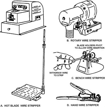
Chapter 2 WIRING TECHNIQUES Learning Objectives Upon completing this chapter, you should be able to: 1. State the basic requirements for any splice and terminal connection, including the preferred wire- stripping method. 2. State the reason the ends of the wire are clamped down after a Western Union splice has been made. 3. Explain the major advantage of the crimped terminal over the soldered terminal. 4. Name the two types of insulation commonly used for noninsulated splices and terminal lugs. 5. State an advantage of using preinsulated terminal lugs and the color code used for each. 6. Explain the procedures for crimping terminal lugs with a hand crimp tool. 7. Recall the physical description and operating procedures for the HT-900B/920B compressed air/nitrogen heating tool. 8. Recall the safety precautions for using the compressed air/nitrogen heating tool. 9. Recall the procedures, precautions, and tools associated with soldering. 10. Explain the procedures and precautions for tinning wire. 11. Recall the types of soldering irons and their uses. 12. State the purposes and required properties of flux. 13. State the purpose for lacing conductors. 14. Recall when double lacing of wire bundles is required. 15. Recall the requirements for using spot ties. WIRING TECHNIQUES This chapter will assist you in learning the basic skills of proper wiring techniques. It explains the different ways to terminate and splice electrical conductors. It also discusses various soldering techniques that will assist you in mastering the basic soldering skills. The chapter ends with a discussion of the procedure to be followed when you lace wire bundles within electrical and electronic equipment. CONDUCTOR SPLICES and TERMINAL CONNECTIONS Conductor splices and connections are an essential part of any electrical circuit. When conductors join each other or connect to a load, splices or terminals must be used. Therefore, it is important that they be properly made. Any electrical circuit is only as good as its weakest link. The basic requirement of any splice or connection is that it be both mechanically and electrically as sound as the conductor or device with which it is used. Quality workmanship and materials must be used to ensure lasting electrical contact, physical strength, and insulation. The most common methods of making splices and connections in electrical cables is explained in the discussion that follows. INSULATION REMOVAL The preferred method of removing insulation is with a wire-stripping tool, if available. a sharp knife may also be used. Other typical wire strippers in use in the Navy are illustrated in figure 2-1. The hot- blade, rotary, and bench wire strippers (views A, B, and C, respectively) are usually found in shops where large wire bundles are made. When using any of these automatic wire strippers, follow the manufacturer's instructions for adjusting the machine; this avoids nicking, cutting, or otherwise damaging the conductors. The hand wire strippers are common hand tools found throughout the Navy. The hand wire strippers (view D of figure 2-1) are the ones you will most likely be using. Wire strippers vary in size according to wire size and can be ordered for any size needed.
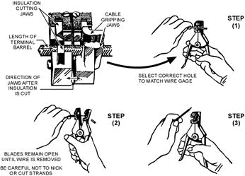
Figure 2-1. - Typical wire-stripping tools. Hand Wire Stripper The procedure for stripping wire with the hand wire stripper is as follows (refer to figure 2-2):
Figure 2-2. - Stripping wire with a hand stripper. 1. Insert the wire into the center of the correct cutting slot for the wire size to be stripped. The wire sizes are listed on the cutting jaws of the hand wire strippers beneath each slot. 2. After inserting the wire into the proper slot, close the handles together as far as they will go. 3. Slowly release the pressure on the handles so as not to allow the cutting blades to make contact with the stripped conductor. On some of the newer style hand wire strippers, the cutting jaws have a safety lock that helps prevent this from happening. Continue to release pressure until the gripper jaws release the stripped wire, then remove. Knife Stripping A sharp knife may be used to strip the insulation from a conductor. The procedure is much the same as for sharpening a pencil. The knife should be held at approximately a 60º angle to the conductor. use extreme care when cutting through the insulation to avoid nicking or cutting the conductor. This procedure produces a taper on the cut insulation as shown in figure 2-3.
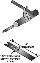
Figure 2-3. - Knife stripping. Locally Made Hot-Blade Wire Stripper If you are required to strip a large number of wires, you can use a locally made hot-blade stripper (figure 2-4) as follows:
Figure 2-4. - Locally made hot-blade stripper. 1. In the end of a piece of copper strip, cut a sharp-edged "V." At the bottom of the "V," make a wire slot of suitable diameter for the size wire to be stripped. 2. Fasten the copper strip around the heating element of an electric soldering iron as shown in figure 2-4. The iron must be rated at 100 watts or greater in order to transfer enough heat to the copper strip to melt the wire insulation. 3. Lay the wire or cable to be stripped in the "V"; a clean channel will be melted in the insulation. 4. Remove the insulation with a slight pull. General Wire-Stripping Instructions When stripping wire with any of the tools mentioned, observe the following precautions: 1. Do not attempt to use a hot-blade stripper on wiring with glass braid or asbestos insulation. These insulators are highly heat resistant. 2. When using the hot-blade stripper, make sure the blades are clean. Clean the blades with a brass wire brush as necessary. 3. Make sure all stripping blades are sharp and free from nicks, dents, and so forth. 4. When using any type of wire stripper, hold the wire perpendicular to the cutting blades. 5. Make sure the insulation is clean-cut with no frayed or ragged edges; trim if necessary. 6. Make sure all insulation is removed from the stripped area. Some types of wire are supplied with a transparent layer between the conductor and the primary insulation. If this is present, remove it. 7. When the hand strippers are used to remove lengths of insulation longer than 3/4 inch, the stripping procedure must be done in two or more operations. The strippers will only strip about 3/4 inch at one time. 8. Retwist strands by hand, if necessary, to restore the natural lay and tightness of the strands. 9. Strip aluminum wires with a knife as described earlier. Aluminum wire should be stripped very carefully. Care should be taken not to nick the aluminum wire as the strands break very easily when nicked. Q1. What are the basic requirements for any splice or terminal connection? Q2. What is the preferred method for stripping wire? Q3. What stripping tool would NOT be used to strip glass braid insulation? Q4. What tool should be used to strip aluminum wire? TYPES of SPLICES There are six commonly used types of splices. Each has advantages and disadvantages for use. Each splice will be discussed in the following section. Western Union Splice The Western Union splice joins small, solid conductors. Figure 2-5 shows the steps in making a Western Union splice.
Figure 2-5. - Western Union splice. 1. Prepare the wires for splicing. Enough insulation is removed to make the splice. The conductor is cleaned. 2. Bring the wires to a crossed position and make a long twist or bend in each wire. 3. Wrap one end of the wire and then the other end four or five times around the straight portion of each wire. 4. Press the ends of the wires down as close as possible to the straight portion of the wire. This prevents the sharp ends from puncturing the tape covering that is wrapped over the splice. The various types of tape and their uses are discussed later in this chapter. Staggering Splices Joining small multiconductor cables often presents a problem. Each conductor must be spliced and taped. If the splices are directly opposite each other, the overall size of the joint becomes large and bulky. a smoother and less bulky joint can be made by staggering the splices. Figure 2-6 shows how a two-conductor cable is joined to a similar size cable by using a Western Union splice and by staggering the splices. Care should be taken to ensure that a short wire from one side of the cable is spliced to a long wire, from the other side of the cable. The sharp ends are then clamped firmly down on the conductor. The figure shows a Western Union splice, but other types of splices work just as well.
Figure 2-6. - Staggering splices. Rattail Joint A splice that is used in a junction box and for connecting branch circuits is the rattail joint (figure 2-7).
Figure 2-7. - Rattail joint. Wiring that is installed in buildings is usually placed inside long lengths of steel or aluminum pipe called a conduit. Whenever branch or multiple circuits are needed, junction boxes are used to join the conduit. To create a rattail joint, first strip the insulation off the ends of the conductors to be joined. You then twist the wires to form the rattail effect. This type of splice will not stand much stress. Fixture Joint The fixture joint is used to connect a small-diameter wire, such as in a lighting fixture, to a larger diameter wire used in a branch circuit. Like the rattail joint, the fixture joint will not stand much strain. Figure 2-8 shows the steps in making a fixture joint. The first step is to remove the insulation and clean the wires to be joined. After the wires are prepared, the fixture wire is wrapped a few times around the branch wire. The end of the branch wire is then bent over the completed turns. The remainder of the bare fixture wire is then wrapped over the bent branch wire. Soldering and taping completes the job.
Knotted Tap Joint All the splices discussed up to this point are known as butted splices. Each was made by joining the free ends of the conductors together. Sometimes, however, it is necessary to join a branch conductor to a continuous wire called the main wire. Such a junction is called a tap joint. The main wire, to which the branch wire is to be tapped, has about 1 inch of insulation removed. The branch wire is stripped of about 3 inches of insulation. The knotted tap is shown in figure 2-9.
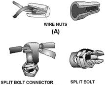
Figure 2-9. - Knotted tap joint. The branch wire is laid behind the main wire. About three-fourths of the bare portion of the branch wire extends above the main wire. The branch wire is brought under the main wire, around itself, and then over the main wire to form a knot. The branch wire is then wrapped around the main conductor in short, tight turns; and the end is trimmed off. The knotted tap is used where the splice is subject to strain or slippage. When there is no strain, the knot may be eliminated. Wire Nut and Split Bolt Splices The wire nut (view a of figure 2-10) is a device commonly used to replace the rattail joint splice. The wire nut is housed in plastic insulating material. To use the wire nut, place the two stripped conductors into the wire nut and twist the nut. In so doing, this will form a splice like the rattail joint and insulate itself by drawing the wire insulation into the wire nut insulation.
Figure 2-10. - Wire nut and split bolt splices. The split bolt splice (view B of figure 2-10) is used extensively to join large conductors. In the illustration, it is shown replacing the knotted tap joint. The split bolt splice can also be used to replace the "butted" splices mentioned previously when using large conductors. Q5. Why are the ends of the wire clamped down after a Western Union splice is made? Q6. Why are splices staggered on multiconductor cables? Q7. Where is the rattail joint normally used? Q8. Which type of splice is used to splice a lighting fixture to a branch circuit? SPLICE INSULATION The splices we have discussed so far are usually insulated with tape. The following discussion will cover some characteristics of rubber, friction, and plastic insulation tapes. Rubber Tape Latex (rubber) tape is a splicing compound. It is used where the original insulation was rubber. The tape is applied to the splice with a light tension so that each layer presses tightly against the one beneath it. This pressure causes the rubber tape to blend into a solid mass. Upon completion, insulation similar to the original is restored. In roll form, there is a layer of paper or treated cloth between each layer of rubber tape. This layer prevents the latex from fusing while still on the roll. The paper or cloth is peeled off and discarded before the tape is applied to the splice. The rubber splicing tape should be applied smoothly and under tension so no air space exists between the layers. Start the first layer near the middle of the joint instead of the end. The diameter of the completed insulated joint should be somewhat greater than the overall diameter of the original wire, including the insulation. Warning Some rubber tapes are made for special applications. These types are semiconducting and will pass electrical current, which presents a shock hazard. These types of tape are packaged similar to the latex rubber tape. Care should be taken to insulate splices only with latex rubber insulating tape. Friction Tape Putting rubber tape over the splice means that the insulation has been restored to a great degree. It is also necessary to restore the protective covering. Friction tape is used for this purpose. It also provides a minor degree of electrical insulation. Friction tape is a cotton cloth that has been treated with a sticky rubber compound. It comes in rolls similar to rubber tape except that no paper or cloth separator is used. Friction tape is applied like rubber tape; however, it does not stretch. The friction tape should be started slightly back on the original insulation. Wind the tape so that each turn overlaps the one before it. Extend the tape over onto the insulation at the other end of the splice. From this point, a second layer is wound back along the splice until the original starting point is reached. Cutting the tape and firmly pressing down the ends completes the job. When proper care is taken, the splice and insulation can take as much abuse as the rest of the original wire. Plastic Electrical Tape Plastic electrical tape has come into wide use in recent years. It has certain advantages over rubber and friction tape. For example, it can withstand higher voltages for a given thickness. Single thin layers of certain plastic tape will withstand several thousand volts without breaking down. However, to provide an extra margin of safety, several layers are usually wound over the splice. The extra layers of thin tape add very little bulk. The additional layers of plastic tape provide the added protection normally furnished by friction tape. Plastic electrical tape usually has a certain amount of stretch so that it easily conforms to the contour of the splice. Q9. Which of the splices discussed is NOT a butted splice?
Q10. Why is friction tape used in splicing? TERMINAL LUGS Since most cable wires are stranded, it is necessary to use terminal lugs to hold the strands together to aid in fastening the wires to terminal studs (see figure 2-11). The terminals used in electrical wiring are either of the soldered or crimped type. Terminals used in repair work must be of the size and type specified on the electrical wiring diagram for the particular equipment. |
||||||||||||||||||||||||||||||||||||||||||||||||||


