Introduction to Electrical Conductors, Wiring Techniques, and Schematic Reading
|
||||||||||||||||||||||||||||||||||||||||||||||||||
|
NEETS Module 4 − Introduction to Electrical Conductors, Wiring Techniques, and Schematic Reading Pages i, 1−1, 1−11, 1−21, 2−1, 2−11, 2−21, 2−31, 2−41, 3−1, 3−11, 3−21, 4−1, 4−11, Index
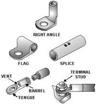
Figure 2-11. - Noninsulated terminal lugs and splices. The increased use of crimp-on terminals is due to the limitations of soldered terminals. The quality of soldered connections depends mostly upon the operator's skill. Other factors, such as temperature, flux, cleanliness, oxides, and insulation damage due to heat, also add to defective connections. Solder-type connections are covered later in this chapter. An advantage of the crimp-on solderless terminal lugs is that they require relatively little operator skill to use. Another advantage is that the only tool needed is the crimping tool. This allows terminal lugs to be applied with a minimum of time and effort. The connections are made rapidly, are clean, and uniform in construction. Because of the pressures exerted and the material used, the crimped connection or splice, properly made, is both mechanically and electrically sound. Some of the basic types of terminals are shown in figure 2-11. There are several variations of these basic types, such as the use of a slot instead of a terminal hole, three- and four-way splice-type connectors, and others. Since the Navy uses both copper and aluminum wiring, both copper and aluminum terminals are necessary. Various size terminal or stud holes may be found for each of the different wire sizes. a further refinement of the solderless terminals and splices is the insulated type. The barrel of the terminal or splice is enclosed in an insulated material. The insulation is compressed along with the terminal barrel when it is crimped, but is not damaged in the process. This rids you of the need for taping or tying an insulating sleeve over the joint. There are several different types of crimping tools used with copper terminals. However, you will normally be concerned only with wire sizes AWG (American Wire Gauge) 10 or smaller. For wire of these sizes, a small plier-type crimper is used to crimp on uninsulated terminals, as shown in figure 2-12. The small plier-type crimper has several sizes of notches for the different size terminals. Care should be used to select the correct size crimping tool for the particular terminal.
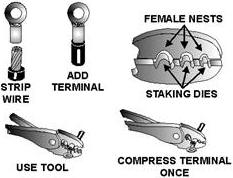
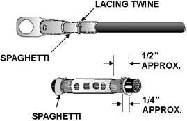
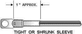
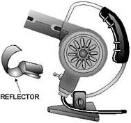
Figure 2-12. - Crimping small copper uninsulated terminals. NONINSULATED TERMINAL and SPLICE INSULATION When noninsulated terminals and splices are used, some form of insulation must be used to cover the bare conductor. The two most common forms of insulator used for terminals and splices are transparent tubing (commonly called spaghetti) and heat-shrinkable tubing. If spaghetti is used, it must be tied with lacing twine, as illustrated in figure 2-13. Heat-shrinkable tubing is shrunk to the desirable size by applying dry heat. It is also a good way to insulate terminals and splices, as illustrated in figure 2-14. This tubing shrinks to approximately one-half its original diameter when heated with an electrical hot-air gun (figure 2-15). Here are the steps for using the hot-air gun:
Figure 2-13. - Spaghetti tied with lacing twine.
Figure 2-14. - Shrunken sleeve.
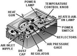
Figure 2-15. - Typical hot-air gun. 1. Hold the heat source 4 to 5 inches away from the wire. Apply a heat of 275º F to 300º F for about 30 seconds. Rotate the wire while applying the heat so that the heat is evenly distributed. 2. Remove the heat as soon as the tubing conforms to the shape of the wire. Allow the tubing to cool for at least 30 seconds before handling. Caution Do not apply heat higher than 300º F as this may damage the wire. Do not continue to apply heat after the tubing has shrunk onto the wire. Further application of heat will not cause additional shrinkage of the tubing. COMPRESSED AIR/NITROGEN Heating TOOL The compressed air/nitrogen heating tool (figure 2-16) is a new tool in the fleet and was designed as a portable source of heat. This tool is safe for use around fueled aircraft because an open heating element is not required. The compressed air/nitrogen heating tool can be used on heat-shrinkable tubing.
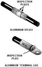
Figure 2-16. - Compressed air/nitrogen heating tool. The compressed air/nitrogen heating tool comes in two styles: ac or dc electrical power supplies. The power requirements are listed in table 2-1 for both styles. Table 2-1. - Compressed Air/Nitrogen Heating Tool Power Requirements Electrical Power, HT-900B 115 VAC, 50-400 Hz, single-phase, 7 Amps Electrical Power, HT-920B 220 VAC, 50-400 Hz, single-phase, 3.5 Amps Heat gun output temperature 550-920°F (290-495°C) Compressed air/nitrogen 80-200 psig, 4 SCFM (Dry and oil-free) Refer to the operator's manual for safe operating procedures for the compressed air/nitrogen heating tool. a brief summary of these procedures follows: 1. Push down and fully turn the air regulator knob counterclockwise. This is to ensure that the air regulator is off. 2. Remove the dust cap from the air inlet nipple. The inlet nipple is what we connect the air or nitrogen source line to. Warning If nitrogen is used, make sure that you are in a well-ventilated area. Using nitrogen is a poorly ventilated area. Using nitrogen is a poorly ventilated area can result in suffocation. Caution As noted in table 2-1, the compressed air/nitrogen source CANNOT be greater than 200 psig. 3. Attach the air/nitrogen hose to the inlet nipple, making sure there is a firm connection. 4. Once the air/nitrogen source is properly attached, push down and turn the air regulator knob clockwise until the pressure on the air pressure gauge indicates between 5 to 7 psig. 5. Plug in the power cord to an appropriate grounded power supply. 6. Set the power switch to the ON position. The power lamp and heated-air-on lamp will both illuminate. (If the lights do not come on, check the switch on the gun handle. The switch must be positioned toward the front of the handle.) 7. There is a 1-minute warm-up time. During this warm-up period, ensure that the indicated air pressure increases to 10 to 15 psig on the air-pressure gauge. 8. You can now adjust the temperature control knob to the desired temperature setting. 9. You can turn the air/nitrogen pressure off and on to the gun without powering down the module by using the switch mounted on the gun handle. After you complete your task with the compressed air/nitrogen heating tool, use the following shutdown procedures: 1. Push down and fully turn the air regulator knob counterclockwise. Observe that the air pressure gauge indication drops to 0 psig and the heated air lamp goes out. 2. Position the switch on the heating gun toward the rear of the handle. 3. Place the power switch to the ofF position and observe that the power lamp goes out. 4. Allow the air/nitrogen to flow for a minimum of 1 minute to cool the heating gun. (This procedure is done to extend the life of the heating element.) 5. Disconnect the power connecter from the power source. 6. Turn off air/nitrogen source at place of origin and disconnect. 7. Disconnect the compressed air/nitrogen hose from the air inlet nipple and install the dust cap on the air inlet nipple. Noninsulated Copper Terminals The procedure for crimping a copper terminal (noninsulated) to a copper wire is as follows: 1. With a wire stripper, trim the insulation from the wire about one thirty-second of an inch longer than the length of the terminal barrel. When using a wire stripper, be sure to use the correct size stripping slot for the wire size used. Otherwise, all the insulation will not be removed or, if the slot is too small, the outside strands of the conductor will be nicked and consequently weakened. When a knife is used for stripping wire, care should be used to prevent nicking the strands. Slip the spaghetti or heat-shrinkable tubing over the wire and back far enough to be out of the way of the crimping operation. 2. Slip the terminal barrel over the bared wire end and up against the insulation. Make certain that all wire strands are inside the tubular barrel of the terminal. 3. Center the terminal barrel in the female nest of the plier jaws as shown in figure 2-12 so that the indentation formed by the staking die will be in the center of the barrel. Crimp until the pliers reach their stop or limit. This is necessary for a good mechanical and electrical connection. 4. Slip the tubular insulation down over the terminal barrel so that it extends a little beyond the barrel. Tie it in place if spaghetti is used. If heat-shrinkable tubing is used, shrink with a heat gun. Q11. What is a major advantage of the crimped terminal over the soldered terminal? Q12. What are the two types of insulation most commonly used for noninsulated splices and terminal lugs? Q13. What is the maximum allowable temperature that should be used on heat-shrinkable tubing? Q14. What is the maximum allowable source pressure that can be used with the compressor air/nitrogen heating tool? ALUMINUM TERMINALS and SPLICES Terminals that are used with aluminum wire are made of aluminum. Proper crimping is more difficult with these terminals because of such factors as aluminum creep and softness. Aluminum wire has an undesirable characteristic called aluminum creep. Aluminum has the tendency to actually move away from the point where pressure is applied. This is not only true during the crimping operation but also takes place during temperature changes. The aluminum wire is softer than the terminal lugs and splice connectors and contracts faster than the connector when the temperature drops. This causes the wires to creep away from the crimped connections, which, in turn, causes loose connections. The softness of aluminum wire also makes it subject to being cut or nicked during stripping. You should be careful never to use an aluminum terminal with copper wire or a copper terminal with aluminum wire because of electrolysis. Electrolysis is the chemical action that takes place when an electric current passes through two dissimilar metals. This chemical action corrodes (eats away) the metal. Also, never use the aluminum crimping tool for crimping other than the aluminum terminals. Aluminum terminal lugs and splices are not insulated, so you must use spaghetti or heat-shrinkable tubing for insulation as discussed earlier. The barrels of several styles of larger size aluminum terminal lugs are filled with a petroleum abrasive compound. This compound causes a grinding action during the crimping operation. This removes the oxide film from the aluminum. It also prevents the oxide film from reforming in the connection. All aluminum terminals and splices have an inspection hole to allow checking the depth of wire insertion. This hole is sealed with a removable plug, which also serves to hold in the oxide-inhibiting compound (figure 2-17).
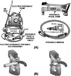
Figure 2-17. - Aluminum terminal lug and splice. It is recommended that only power-operated crimping tools be used to install large aluminum terminal lugs and splices. (See view a of figure 2-18.)
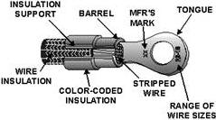
Figure 2-18. - Power crimping tools. The steps used for crimping an aluminum terminal or splice to an aluminum wire (view B of figure 2-18) are as follows: 1. Carefully remove the conductor insulation. Do not cut or nick the aluminum conductors. Do not wire-brush or scrape the aluminum conductor (the compound in the terminal or splice barrel will clean it satisfactorily). 2. Remove the protective foil wrapping from the terminal or splice and check the amount of compound in the terminal barrel. It should be one-fourth to one-half full. 3. Slip the spaghetti or heat-shrinkable tubing over the wire and back far enough to be out of the way of the crimping operation. Insert the stripped conductor the full length of the terminal or splice barrel. While doing this, leave the plug over the inspection hole. This allows the compound to be forced in and around the strands. 4. Center the terminal lug or splice in the crimping tool. 5. Actuate the power crimping tool. 6. Wipe off the excess compound. Inspect the joint with a probe through the inspection hole. The end of the conductor should come to the edge of the inspection hole. 7. Slip the tubular insulation down over the terminal or splice barrel. Tie it in place if spaghetti is used. If using heat-shrinkable tubing, shrink with a heat gun. Q15. Should aluminum wire be cleaned prior to installing an aluminum terminal lug or splice? Q16. What tools should be used to install large aluminum terminal lugs and splices? Q17. Why should a lock washer never be used with an aluminum terminal? Improper crimping procedures eventually cause terminal failure. Be especially careful of undercrimping, overcrimping, using wrong crimping tools, improper cleaning methods, and cutting or nicking the conductors. a loose contact allows an oxide film to form between the wire and the terminal. This results in increased resistance, and the resistance causes heat. The heat accelerates deterioration, and eventually a failure results. PREINSULATED COPPER TERMINAL LUGS and SPLICES The use of preinsulated terminal lugs and splices has become the most common method for copper wire termination and splicing in recent years. It is by far the best and easiest method. There are many tools used for crimping terminal lugs and splices. Hand, portable power, and stationary power tools are available for crimping terminal lugs. These tools crimp the barrel to the conductor and, at the same time, form the insulation support to the wire insulation. The power tools, both stationary and portable, are usually found in large shops where wire bundles are made up. In the next paragraphs, we will discuss the more common hand-crimping tools you will most likely be using in your day-to-day work. TERMINATING COPPER Wire WITH PREINSULATED TERMINAL LUGS Small-diameter copper wires are terminated with solderless, preinsulated copper terminal lugs. As shown in figure 2-19, the insulation is part of the terminal lug. It extends beyond the barrel so that it covers a portion of the wire insulation. This makes the use of spaghetti or heat-shrinkable tubing unnecessary. Preinsulated terminal lugs also have an insulation support (a metal reinforcing sleeve) beneath the insulation for extra supporting strength of the wire insulation. Some preinsulated terminals fit more than one size of wire. The insulation is color coded, and the range of wire sizes is marked on the tongue. This identifies the wire sizes that can be terminated with each of the terminal lug sizes. (See table 2-2.)
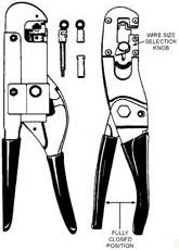
Figure 2-19. - Preinsulated straight copper terminal lug. Table 2-2. - Color Coding of Copper Terminal Lug or Splice Insulation Color of Terminal Lug or Splice Insulation To Be used on Wire Sizes Yellow (Bright).................................... #26 - #24 Red...................................................... #22 - #20, #18 Blue...................................................... #16 - #14 Yellow (Dull).............................................. #12 - #10 For crimping small copper terminal lugs, several hand-crimping tools can be used for wire sizes AWG 26 through 10 (figure 2-20). These hand-crimping tools have a self-locking ratchet, which prevents the tool from opening until the crimp is completed. Some of these tools have a color-coded selector knob to match the color-coded terminal lug or splice being used. Other tools have a replaceable set of dies for several wire sizes. The hand-crimping procedure for preinsulated copper terminal lugs in wire sizes No. 26 through No. 10 with the standard hand-crimp tool is as follows:
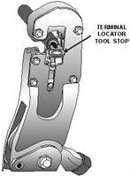
Figure 2-20. - Hand-crimping tools. 1. Strip the wire insulation using the recommended stripping procedures already discussed. 2. Ensure that the tool handles are fully open and the proper die set has been installed correctly. 3. Insert the terminal lug, tongue first, into the wire side of the hand tool barrel crimping jaws. Be certain the terminal lug barrel butts flush against the tool stop on the locator. See figure 2-21 for the correct insertion method.
Figure 2-21. - Crimping tool with terminal lug inserted. |
||||||||||||||||||||||||||||||||||||||||||||||||||