Introduction to Electrical Conductors, Wiring Techniques, and Schematic Reading
|
||||||||||||||||||||||||||||||||||||||||||||||||||
|
NEETS Module 4 − Introduction to Electrical Conductors, Wiring Techniques, and Schematic Reading Pages i, 1−1, 1−11, 1−21, 2−1, 2−11, 2−21, 2−31, 2−41, 3−1, 3−11, 3−21, 4−1, 4−11, Index
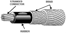
Generally, except for overhead transmission lines, wires or cables are protected by some form of covering. The covering may be some type of insulator like rubber or plastic. Over this, additional layers of fibrous braid or tape may be used and then covered with a finish or saturated with a protective coating. If the wire or cable is installed where it is likely to receive rough treatment, a metallic coat should be added. The materials used to make up the protection for a wire or cable are grouped into one of two categories: nonmetallic or metallic. Q29. If a cable is installed where it receives rough treatment, what should be added? NONMETALLIC PROTECTION The category of nonmetallic protective coverings is divided into three areas. These areas are (1) according to the material used as the covering, (2) according to the saturant in which the covering was impregnated, and (3) according to the external finish on the wire or cable. These three areas reflect three different methods of protecting the wire or cable. These methods allow some wire or cable to be classified under more than one category. Most of the time, however, the wire or cable will be classified based upon the material used as the covering regardless of whether or not a saturant or finish is applied. Many types of nonmetallic materials are used to protect wires and cables. Fibrous braid is by far the most common and will be discussed first. Fibrous Braid Fibrous braid is used extensively as a protective covering for cables. This braid is woven over the insulation to form a continuous covering without joints (figure 1-15). The braid is generally saturated with asphalt, paint, or varnish to give added protection against moisture, flame, weathering, oil, or acid. Additionally, the outside braid is often given a finish of stearin pitch and mica flakes, paint, wax, lacquer, or varnish depending on the environment where the cable is to be used.
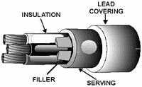
Figure 1-15. - Fibrous braid covering. The most common type of fibrous braid is woven from light, standard, or heavy cotton yarn. Cotton yarn comes in different colors, which allows color-coding of the individual conductors. Cotton will not withstand all the possible environments in which a cable may be laid. Other materials currently being used to make fibrous braid are glazed cotton, seine twine or hawser cord, hemp, paper and cotton, jute, asbestos, silk, rayon, and fibrous glass. The choice of which material to use depends on the strength needed in the cable as well as how resistant it must be to its environment. Fibrous Tape Fibrous tape coverings are frequently used as a part of the protective covering of cables. The material of tape coverings is made into the tape before application to the cable. The material in yarns for braid covering is woven into fabric during the application to the cable. When tape covering is used, it is wrapped helically around the cable with each turn overlapping the previous turn. The most common types of fibrous tape are rubber-filled cloth tape and a combination of cotton cloth and rubber. Except for duct tape, tape covering is never used as the outer covering on a cable. Tape coverings are used directly over the insulation of individual conductors and for the inner covering over the assembled conductors of a multiconductor cable. Frequently, tape coverings are used under the sheath of a lead-sheathed cable. Duct tape, which is made of heavy canvas webbing saturated with an asphalt compound, is often used over a lead-sheathed cable for protection against corrosion and mechanical injury. Q30. How many categories of nonmetallic protective coverings are there? Q31. What is the most common type of nonmetallic material used to protect wires and cables? Q32. What are the most common types of fibrous tape? Woven Covers Woven covers, commonly called loom, are used when exceptional abrasion-resistant qualities are required. These covers are composed of thick, heavy, long-fibered cotton yarns woven around the cable in a circular loom, much like that used on a fire hose. They are not braids, although braid covering are also woven; they are designated differently. Rubber and Synthetic Coverings Rubber and synthetic coverings are not standardized. Different manufactures have their own special compounds designated by individual trade names. These compounds are different from the rubber compounds used to insulate cable. These compounds have been perfected not for insulation qualities but for resistance to abrasion, moisture, oil, gasoline, acids, earth solutions, and alkalies. None of these coverings will provide protection against all types of exposure. Each covering has its own particular limitations and qualifications. Jute and Asphalt Coverings Jute and asphalt coverings are commonly used as a cushion between cable insulation and metallic armor. Frequently, they are also used as a corrosive-resistant covering over a lead sheath or metallic armor. Jute and asphalt coverings consist of asphalt-impregnated jute yarn heli-wrapped around the cable or of alternate layers of asphalt-impregnated jute yarn. These coverings serve as a weatherproofing. Unspun Felted Cotton Unspun felted cotton is commonly used only in special classes of service. It is made as a solid felted covering for a cable. Q33. What materials are commonly used as cushions between cable insulation and metallic armor? METALLIC PROTECTION Metallic protection is of two types: sheath or armor. As with all wires and cables, the type of protection needed will depend on the environment where the wire or cable will be used. Metallic Sheath Cables or wires that are continually subjected to water must be protected by a watertight cover. This watertight cover is either a continuous metal jacket or a rubber sheath molded around the cable. Figure 1-16 is an example of a lead-sheathed (jacketed) cable used in power work. This cable is a standard three-conductor type. Each conductor is insulated and then wrapped in a layer of rubberized tape. The conductors are twisted together, and rope or fillers are added to form a round core. Over this is wrapped a second layer of tape called a serving. Finally, a lead sheath is molded around the cable.
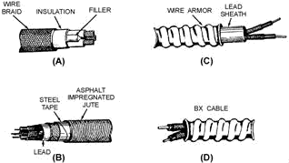
Figure 1-16. - Lead-sheathed cable. Lead-sheathed cable is one of three types currently being used: alloy lead, pure lead, and reinforced lead. An alloy-lead sheath is much like a pure lead sheath but is manufactured with 2-percent tin. This alloy is more resistant to gouging and abrasion during and after installation. Reinforced lead sheath is used mainly for oil-filled cables where high internal pressures can be expected. Reinforced lead sheath consists of a double lead sheath. a thin tape of hard-drawn copper, bronze, or other elastic metal (preferably nonmagnetic) is wrapped around the inner sheath. This tape gives considerable additional strength and elasticity to the sheath, but must be protected from corrosion. For this reason, a second lead sheath is applied over the tape. Metallic Armor Metallic armor provides a tough protective covering for wires and cables. The type, thickness, and kind of metal used to make the armor depend on three factors: (1) the use of the conductors, (2) the environment where the conductors are to be used, and (3) the amount of rough treatment that is expected. Figure 1-17 shows three examples of metallic armor cable: wire braid, steel tape, and wire armor.
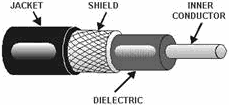
Figure 1-17. - Metallic armor cable. Wire-BRAID ARMOR. - Wire-braid armor (view a of figure 1-17 ), also known as basket-weave armor, is used when light and flexible protection is needed. Wire braid is constructed much like fibrous braid. The metal is woven directly over the cable as the outer covering. The metal used in this braid is galvanized steel, bronze, copper, or aluminum. Wire-braid armor is mainly for shipboard use. STEEL TAPE. - a second type of metallic armor is steel tape. Steel tape covering (view B of figure 1-17) is wrapped around the cable and then covered with a serving of jute. There are two types of steel tape armor. The first is called interlocking armor. Interlocking armor is applied by wrapping the tape around the cable so that each turn is overlapped by the next and is locked in place. The second type is flat- band armor. Flat-band armor consists of two layers of steel tape. The first layer is wrapped around the cable but is not overlapped. The second layer is then wrapped around the cable covering the area that was not covered by the first layer. Wire ARMOR. - Wire armor is a layer of wound metal wire wrapped around the cable. Wire armor is usually made of galvanized steel and can be used over a lead sheath (see view C of figure 1-17). It can be used with the sheath as a buried cable where moisture is a concern, or without the sheath (view D of figure 1-17) when used in buildings. Q34. What are the two types of metallic protection? Q35. What are the three types of lead-sheathed cables? Q36. What are the three examples of metallic armor cable that were discussed? COAXIAL CABLE Coaxial cable (figure 1-18) is defined as two concentric wires, cylindrical in shape, separated by a dielectric of some type. One wire is the center conductor and the other is the outer conductor. These conductors are covered by a protective jacket. The protective jacket is then covered by an outer protective armor.
Figure 1-18. - Coaxial cable. Coaxial cables are used as transmission lines and are constructed to provide protection against outside signal interference. Summary In this chapter you learned that conductors are the means for tying the various components of an electrical or electronic system together. Many factors determine the type of conductor to be used in a specific application. In order for you to compare the different types and sizes of conductors, we discussed the following factors: Unit Size - The unit size of a conductor is the mil-foot. a mil-foot is a circular conductor 1foot long with a diameter of 1 mil (0.001 inch, or one-thousandth of an inch).
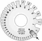
Conductor Sizes - The square mil and the circular mil are the units of measure used to determine the cross-sectional area of electrical conductors. The square mil, as it relates to a square conductor, is the cross-sectional area of a square conductor that has a side of 1 mil. The circular mil is the cross-sectional area of a circular conductor having a diameter of 1 mil. The circular mil area (CMA) of a conductor is computed by squaring the diameter of the circular conductor is mils. Thus, a wire having a diameter of 4 mils (0.004 inch) has a CMA of 42, or 16 circular mils. If the conductor is stranded, the CMA for a strand is computed, and the CMA for the conductor is computed by multiplying the CMA of the strand by the number of strands. The relationship of the square mil to the circular mil is determined by comparing the square mil area of a circular conductor having a diameter of 1 mil (A = πr2) to the circular mil area of the same conductor (D2). Therefore, there is 0.7854 square mil to 1 circular mil. There are more circular mils than square mils in a given area. Specific Resistance - The specific resistance of a substance is the resistance in ohms offered by a unit volume (the circular-mil-foot) to the flow of electric current. The three factors that are used to calculate the specific resistance of a particular conductor are (1) its length, (2) its cross-sectional area, and (3) the specific resistance of a unit volume of the substance from which the conductor is made. The specific resistance for various sizes and lengths of standard solid copper wire can be determined by the use of tables. Wire Gauge - a wire gauge is used to determine the American Standard Wire Gauge size of conductors. The measurement of a bare conductor is taken in the slot, not in the circular area at the bottom of the slot.
Selection of Wire Size - Four factors must be considered in selecting the proper wire size for a particular electrical circuit. These factors are (1) conductor size, (2) the material it's made of, (3) the location of the wire in the circuit, and (4) the type of insulation used. Some of the types of insulation used in a high-temperature environment are FEP, extruded polytetrafluoroethylene, and silicone rubber. The ambient (surrounding) temperature of a conductor is an important part of total conductor heating. Copper-versus-Aluminum Conductors - The two most common metals used for electrical conductors are copper and aluminum. Some advantages of copper over aluminum as a conductor are that copper has higher conductivity, is more ductile, has a higher tensile strength, and can be easily soldered. Two advantages of aluminum wire for carrying electricity over long distances are its lightness and it reduces corona (the discharge of electricity from a wire at high potential). Temperature Coefficient of Resistance - The temperature coefficient of resistance is the amount of increase in the resistance of a 1-ohm sample of a conductor per degree of temperature rise above 0º C. The resistance of copper and other pure metals increases with an increase in temperature. Conductor Insulation - Insulators have a resistance that is so great that, for all practical purposes, they are nonconductors. Two fundamental properties of insulating materials are (1) insulation resistance and (2) the resistance to current leakage through the insulation. Dielectric strength is the ability of the insulation material to withstand potential difference. The dielectric strength of an insulator is determined by raising the voltage on a test sample until it breaks down. Insulating Materials - Some common insulating materials have properties and safety precautions that should be remembered. These are: · The purpose of coating a copper conductor with tin when rubber insulation is used is to prevent the insulation from deteriorating due to chemical action. · When extruded polytetrafluoroethylene insulation is heated, caution should be observed not to breathe the vapors. · The most commonly used insulating materials for extremely high-voltage conductors are varnished cambric and oil-impregnated paper. · Magnet wire is the common name for enamel-insulated wire used in meters, relays, small transformers, motor windings, and so forth. · The Navy is getting away from using asbestos insulation because asbestos fibers can cause lung disease and/or cancer. · Asbestos insulation becomes a conductor when it gets wet.
Conductor Protection - There are several types of conductor protection in use. The type commonly used aboard Navy ships is wire-braid armor. Answers to Questions Q1. Through Q36. A1. To allow comparisons between conductors of different sizes and resistance. A2. 375 mils (move the decimal three places to the right). A3. a circular conductor with a diameter of 1 mil and a length of 1 foot. A4. The cross-sectional area of a square conductor with a side of 1 mil. A5. The cross-sectional area of a circular conductor with a diameter of 1 mil. A6. Circular mil area (CMA) = D2 (in mils) x number of strands0.0004 inch = 4 mils (CMA) = 42 x 19 (strands)(CMA) = 16 x 19 = 304 mils. A7. The resistance of a unit volume of a substance. A8. Length, cross-sectional area, and specific resistance of a unit volume of the substance from which the conductor is made. A9. 1,000 ft = 10.4 ohms1,500 ft = 1.5 x 0.4 = 15.6 ohms A10. In the parallel walled slot not the circular area. A11. Conductor size, the material it is made of the location of the wire in a circuit, and the type of insulation used. A12. FEP, extruded polytetrafluoroethylene, and silicone rubber. A13. The heat surrounding the conductor is an important part of total conductor heating. A14. It is light and reduces corona. A15. It has higher conductivity, it is more ductile, it has relatively high tensile strength, and it can be easily soldered. A16. The amount of increase in the resistance of a 1-ohm sample of the conductor per degree of temperature rise above 0º C A17. It increases. A18. Conductors have a very low resistance and insulators have a resistance that is so great that, for all practical purposes, they are nonconductors. A19. Insulation resistance and dielectric strength. A20. The resistance to current leakage through the insulation. A21. The ability of the insulation material to withstand potential difference. A22. By raising the voltage on a test sample until it breaks down. A23. To prevent the rubber insulation from deteriorating due to chemical action. A24. Avoid breathing the vapors when the insulation is heated. A25. Breathing asbestos fibers can cause lung disease and/or cancer A26. It will become a conductor. A27. Varnished cambric and oil-impregnated paper. A28. Magnet wire. A29. Metallic coat. A30. Three. A31. Fibrous Braid. A32. Rubber-filled cloth tape and a combination of cotton cloth and rubber. A33. Jute and Asphalt coverings. A34. Sheath and armor A35. Alloy lead, pure lead, and reinforced lead. A36. Wire braid, steel tape, and wire armor |
||||||||||||||||||||||||||||||||||||||||||||||||||
