Module 16 - Introduction to Test Equipment
Pages i,
1-1,
1-11,
1-21,
2-1,
2-11,
2-21,
3-1,
3-11,
3-21,
3-31,
4-1,
4-11,
4-21,
5-1,
5-11,
5-21,
5-31,
6-1,
6-11,
6-21,
6-31,
6-41, Index
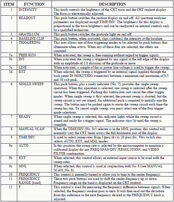
Table 6-1. - Description of Front Panel Controls, Indicators, and Connectors

6-41
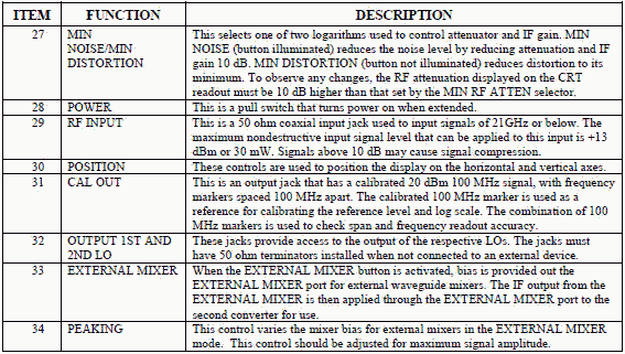
Table 6-1. - Description of Front Panel Controls, Indicators, and Connectors - Continued

6-42
Table 6-1. - Description of Front Panel Controls, Indicators, and Connectors - Continued

6-43
Table 6-1. - Description of Front Panel Controls, Indicators, and Connectors - Continued
 NORMAL INDICATIONS UPON Power ON With power applied (power knob pulled out), the
spectrum analyzer will automatically (upon microcomputer control) go into the following conditions. If you do not
find these indications, there is a probably a problem with the unit.
· Vertical display: 10 dB/div;
· Frequency: 0.00 MHz;
· REF level: +30 dB;
· RF attenuation: 60 dB;
· Frequency range: 0.0 to 1.8 GHz;
· Auto resolution: 1 MHz;
· Resolution bandwidth: 1 MHz;
· Freq Span/Div: Max;
· Triggering: Free run;
·
Readout: On;
· Digital storage: View A/View B On;
6-44
· All other indicators off or inactive.
Summary Now that we have completed this chapter, we will briefly review the more important points covered. a
CATHODE-RAY TUBE (CRT) is used in an oscilloscope to display the waveforms. The CRT used in
oscilloscopes consists of an ELECTRON GUN, a DEFLECTION System, and a
FLUORESCENT SCREEN. The ELECTRON BEAM in an oscilloscope is allowed to be
controlled in any direction by means of HORIZONTAL- and VERTICAL-DEFLECTION PLATES.
VERTICAL-DEFLECTION PLATES are used to show Amplitude of a signal.
HORIZONTAL-DEFLECTION PLATES are used to show TIME and/or Frequency
relationship. A GRATICULE is a calibrated scale of Amplitude VERSUS TIME
that is placed on the face of the CRT. A DUAL-TRACE OSCILLOSCOPE is designed to accept
two vertical inputs at the same time. It uses a single beam of electrons shared by two channels. The
SPECTRUM ANALYZER accepts an electrical input signal and displays the signal's frequency and
amplitude on a CRT display.
Answers to Questions Q1. Through Q18. A-1. Control grid. A-2. The first anode. A-3. Because they bend electron streams
in much the same manner that optical lenses bend light rays. A-4. It accelerates the electrons emerging
from the first anode. A-5. a greater deflection angle.
A-6. a greater deflection angle. A-7. Higher potential. A-8. Slower beam. A-9.
Amplitude and time. A-10. Amplitude.
A-11. Time and/or frequency relationships.
6-45
A-12. To permit wide-angle deflection of the beam. A-13. Deflection factor.
A-14. a CRT, a group of control circuits, power supply, sweep circuitry, and deflection circuitry.
A-15. Lower. A-16. Amplitude, phase, time, and frequency.
A-17. Dual-trace oscilloscopes. A-18. Front end.
6-46
| - |
Matter, Energy,
and Direct Current |
| - |
Alternating Current and Transformers |
| - |
Circuit Protection, Control, and Measurement |
| - |
Electrical Conductors, Wiring Techniques,
and Schematic Reading |
| - |
Generators and Motors |
| - |
Electronic Emission, Tubes, and Power Supplies |
| - |
Solid-State Devices and Power Supplies |
| - |
Amplifiers |
| - |
Wave-Generation and Wave-Shaping Circuits |
| - |
Wave Propagation, Transmission Lines, and
Antennas |
| - |
Microwave Principles |
| - |
Modulation Principles |
| - |
Introduction to Number Systems and Logic Circuits |
| - |
- Introduction to Microelectronics |
| - |
Principles of Synchros, Servos, and Gyros |
| - |
Introduction to Test Equipment |
| - |
Radio-Frequency Communications Principles |
| - |
Radar Principles |
| - |
The Technician's Handbook, Master Glossary |
| - |
Test Methods and Practices |
| - |
Introduction to Digital Computers |
| - |
Magnetic Recording |
| - |
Introduction to Fiber Optics |
| Note: Navy Electricity and Electronics Training
Series (NEETS) content is U.S. Navy property in the public domain. |
|


