|
June 1966 Radio-Electronics
 [Table of Contents] [Table of Contents]
Wax nostalgic about and learn from the history of early electronics.
See articles from Radio-Electronics,
published 1930-1988. All copyrights hereby acknowledged.
|
Being that this Circuit Quiz
appeared in a 1966 issue of Radio-Electronics magazine, the amplifier components
shown are transistors, rather than vacuum tubes. I have to admit to not doing very
well on it. One of the challenges is first determining what the intended function
of the circuit is supposed to be, then you figure out what is wrong with it. Spoiler
alert: I'm going to use circuit A as an example. It is declared to be a voltage
regulator circuit, and the deficiency is the lack of a stable voltage reference.
The architecture is typical of a voltage regulator with the common base setup used
to increase the current supply. However, there is no reason to necessarily assume
the DC IN is not itself already regulated, and the function if merely to increase
the current supply capacity. If that is the case, then the circuit seems sufficient
as shown. Maybe the fact that there is no problem otherwise should tell you make
an assumption about the designer's intention and look for something that would be
suspect under that condition. Anyway, that's my excuse and I'm sticking with it
;-)
Circuit Quiz
 By Marvin Jack Moss By Marvin Jack Moss
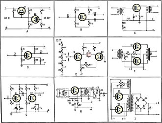
Each of these circuits has one error that will keep it from working as it should
- or from working at all. Can you name each circuit and find the trouble? Assume
component values to be consistent with proper design of the circuit.
Answers below.
Quizzes from vintage electronics magazines such as Popular
Electronics, Electronics-World, QST, and Radio News
were published over the years - some really simple and others not so simple. Robert P. Balin
created most of the quizzes for Popular Electronics. This is a listing
of all I have posted thus far.
- RF Cafe Quiz #71:
Tech Headlines for Week of 3/13/2023
- RF Cafe Quiz #70:
Analog &
RF Filter Basics
- RF Cafe Quiz #69:
RF
Electronics Basics
- RF Cafe Quiz #68:
RF & Analog Company Mergers & Acquisitions in 2017
- RF Cafe Quiz #67:
RF & Microwave Company Name Change History
- RF Cafe Quiz #66:
Spectrum and Network Measurements
- RF Cafe Quiz #65:
Troubleshooting & Repairing Commercial Electrical Equipment
- RF Cafe Quiz #64:
Space-Time Adaptive Processing for Radar
- RF Cafe Quiz #63:
Envelope Tracking Power Amplifiers
- RF Cafe Quiz #62:
Stimson's Introduction to Airborne Radar
- RF Cafe Quiz #61:
Practical Microwave Circuits
- RF Cafe Quiz #60:
Ten Essential Skills for Electrical Engineers
- RF Cafe Quiz #59:
Microwave Circulator Design
- RF Cafe Quiz #58:
Microwave and Millimeter-Wave Electronic Packaging
- RF Cafe Quiz #57:
Frequency-Agile Antennas for Wireless Communications
- RF Cafe Quiz #56:
Tube Testers
and Electron Tube Equipment
- RF Cafe Quiz #55:
Conquer
Radio Frequency
- RF Cafe Quiz #54:
Microwave Mixer Technology and Applications
- RF Cafe Quiz #53:
Chipless RFID Reader Architecture
- RF Cafe Quiz #52:
RF and Microwave Power Amplifiers
- RF Cafe Quiz #51:
Antennas and Site Engineering for Mobile Radio Networks
- RF Cafe Quiz #50:
Microstrip Lines and Slotlines
- RF Cafe Quiz #49:
High-Frequency Integrated Circuits
- RF Cafe Quiz #48:
Introduction to Infrared and Electro-Optical Systems
- RF Cafe Quiz #47:
LCP for Microwave Packages and Modules
- RF Cafe Quiz #46:
RF, Microwave, and Millimeter-Wave Components
- RF Cafe Quiz #45:
Dielectric and Thermal Properties of Materials at Microwave Frequencies
- RF Cafe Quiz #44:
Monopulse Principles and Techniques
- RF Cafe Quiz #43:
Plasma Antennas
- RF Cafe Quiz #42: The Micro-Doppler
Effect in Radar
- RF Cafe Quiz #41: Introduction
to RF Design Using EM Simulators
- RF Cafe Quiz #40: Introduction
to Antenna Analysis Using EM Simulation
- RF Cafe Quiz #39: Emerging
Wireless Technologies and the Future Mobile Internet
- RF Cafe Quiz #38: Klystrons,
Traveling Wave Tubes, Magnetrons, Crossed-Field Amplifiers, and Gyrotrons
- RF Cafe Quiz #37: Component
Reliability for Electronic Systems
- RF Cafe Quiz #36: Advanced
RF MEMS
- RF Cafe Quiz #35: Frequency
Synthesizers: Concept to Product
- RF Cafe Quiz #34: Multi-Gigabit
Microwave and Millimeter-Wave Wireless Communications
- RF Cafe Quiz #33: Battlespace
Technologies: Network-Enabled Information Dominance
- RF Cafe Quiz #32: Modern Communications
Receiver Design and Technology
- RF Cafe Quiz #31: Quantum
Mechanics of Nanostructures
- RF Cafe Quiz #30: OFDMA System
Analysis and Design
- RF Cafe Quiz #29: Cognitive
Radar
- RF Cafe Quiz #28: Human-Centered
Information Fusion
- RF Cafe Quiz #27: Remarkable
Engineers
- RF Cafe Quiz #26: Substrate
Noise Coupling in Analog/RF Circuits
- RF Cafe Quiz #25: Component
Reliability for Electronic Systems
- RF Cafe Quiz #24: Ultra Low
Power Bioelectronics
- RF Cafe Quiz #23: Digital
Communications Basics
- RF Cafe Quiz #22: Remember
the Basics?
- RF Cafe Quiz #21: Wireless
Standards Knowledge
- RF Cafe Quiz #20: Famous First
Names
- RF Cafe Quiz #19: Basic Circuit
Theory
- RF Cafe Quiz #18: Archaic
Scientific Words & Definitions
- RF Cafe Quiz #17: Inventors &
Their Inventions
- RF Cafe Quiz #16: Antennas
- RF Cafe Quiz #15: Numerical
Constants
- RF Cafe Quiz #14: Oscillators
- RF Cafe Quiz #13: General
Knowledge
- RF Cafe Quiz #12: Electronics
Corporations Headquarters
- RF Cafe Quiz #11: Famous Inventors &
Scientists
- RF Cafe Quiz #10: A Sampling
of RF & Wireless Topics
- RF Cafe Quiz #9: A Smorgasbord
of RF Topics
- RF Cafe Quiz #8: Hallmark Decades
in Electronics
- RF Cafe Quiz #7: Radar Fundamentals
- RF Cafe Quiz #6: Wireless Communications
Fundamentals
- RF Cafe Quiz #5: Company Logo
Recognition
- RF Cafe Quiz #4: General RF
Topics
- RF Cafe Quiz #3: General RF/Microwave
Topics
- RF Cafe Quiz #2: General RF
Topics
- RF Cafe Quiz #1: General RF
Knowledge
- Vacuum Tube Quiz,
February 1961 Popular Electronics
- Kool-Keeping Kwiz, June
1970 Popular Electronics
- Find the Brightest
Bulb Quiz, April 1960 Popular Electronics
-
Where Do the Scientists Belong? - Feb 19, 1949 Saturday Evening Post
|
-
What's Your EQ? - April 1967 Radio-Electronics
-
What's Your EQ? -
March 1967 Radio-Electronics
-
What's Your EQ? - December 1964 Radio-Electronics
-
What's Your EQ? - January 1967 Radio-Electronics
-
Wanted: 50,000 Engineers - January 1953 Popular Mechanics
-
What's Your EQ? - August 1964 Radio-Electronics
- Voltage Quiz
- December 1961 Popular Electronics
-
What is It? - June 1941 Popular Science
- What Do You Know
About Resistors? - April 1974 Popular Electronics
-
What's Your EQ? - September 1963 Radio-Electronics
- Potentiometer Quiz - September
1962 Popular Electronics
-
Mathematical Bafflers - March 1965 Mechanix Illustrated
- Op Amp Quiz -
October 1968 Popular Electronics
- Electronic "A"
Quiz - April 1968 Popular Electronics
-
What's Your EQ? - May 1961 Radio-Electronics
-
Popular Science Question Bee - February 1939 Popular Science
-
What is It? - A Question Bee in Photographs - June 1941 Popular Science
-
What's Your EQ? - June 1961 Radio-Electronics
-
What's Your EQ? - June 1964 Radio-Electronics
-
What's Your EQ? - May 1964 Radio-Electronics
-
What's Your EQ? - August 1963 Radio-Electronics
-
What's Your EQ? - May 1963 Radio-Electronics
- Bridge
Function Quiz - September 1969 Radio-Electronics
-
What's Your EQ? - March 1963 Radio-Electronics
-
What's Your EQ? - February 1967 Radio-Electronics
-
Circuit Quiz - June 1966 Radio-Electronics
-
What's Your EQ? - June 1966 Radio-Electronics
- Electronics
Mathematics Quiz - June 1969 Popular Electronics
- Brightest
Light Quiz - April 1964 Popular Electronics
-
What's Your EQ? - April 1963 Radio-Electronics
- Electronics "B" Quiz
- July 1969 Popular Electronics
- Ohm's Law Quiz
- March 1969 Popular Electronics
-
Antenna Quiz - November 1962 Electronics World
- Color Code Quiz
- November 1967 Popular Electronics
- CapaciQuiz
- August 1961 Popular Electronics
- Transformer
Winding Quiz - December 1964 Popular Electronics
-
Audiophile Quiz - November 1957 Radio-electronics
- Capacitor
Function Quiz - March 1962 Popular Electronics
- Greek Alphabet
Quiz - December 1963 Popular Electronics
- Circuit
Designer's Name Quiz - July 19680 Popular Electronics
-
Sawtooth Sticklers Quiz - November 1960 Radio-Electronics
-
Elementary
Radio Quiz - December 1947 Radio-Craft
- Hi-Fi
Quiz - October 1955 Radio & Television News
- Electronics Physics
Quiz - March 1974 Popular Electronics
- A Baffling Quiz
- January 1968 Popular Electronics
- Electronics IQ
Quiz - May 1967 Popular Electronics
- Plug and Jack
Quiz - December 1967 Popular Electronics
- Electronic
Switching Quiz - October 1967 Popular Electronics
- Electronic
Angle Quiz - September 1967 Popular Electronics
- International
Electronics Quiz - July 1967 Popular Electronics
- FM Radio
Quiz - April 1950 Radio & Television News
- Bridge Circuit
Quiz -December 1966 Popular Electronics
- Diode Function
Quiz - August 1965 Popular Electronics
- Diagram Quiz,
August 1966 Popular Electronics
- Quist Quiz - November
1953 QST
- TV Trouble Quiz,
July 1966 Popular Electronics
- Electronics History Quiz,
December 1965 Popular Electronics
- Scope-Trace Quiz,
March 1965 Popular Electronics
-
Electronic
Circuit Analogy Quiz, April 1973
-
Test Your Knowledge of Semiconductors, August 1972 Popular Electronics
- Ganged Switching
Quiz, April 1972 Popular Electronics
- Lamp Brightness
Quiz, January 1969 Popular Electronics
- Lissajous
Pattern Quiz, September 1963 Popular Electronics
- Electronic
Quizoo, October 1962 Popular Electronics
- Electronic
Photo Album Quiz, March 1963 Popular Electronics
- Electronic
Alphabet Quiz, May 1963 Popular Electronics
- Quiz: Resistive?
Inductive? or Capacitive?, October 1960 Popular Electronics
- Vector-Circuit
Matching Quiz, June 1970 Popular Electronics
- Inductance
Quiz, September 1961 Popular Electronics
- RC Circuit Quiz,
June 1963 Popular Electronics
- Diode Quiz, July
1961 Popular Electronics
- Electronic
Curves Quiz, February 1963 Popular Electronics
- Electronic
Numbers Quiz, December 1962 Popular Electronics
- Energy Conversion
Quiz, April 1963 Popular Electronics
- Coil Function
Quiz, June 1962 Popular Electronics
-
Co-Inventors Quiz - January 1965 Electronics World
-
"-Tron" Teasers Quiz - October 1963 Electronics World
- Polarity Quiz
- March 1968 Popular Electronics
-
Television
I.Q. Quiz - October 1948 Radio & Television News
- Amplifier Quiz
Part I - February 1964 Popular Electronics
- Semiconductor
Quiz - February 1967 Popular Electronics
- Unknown
Frequency Quiz - September 1965 Popular Electronics
- Electronics
Metals Quiz - October 1964 Popular Electronics
- Electronics
Measurement Quiz - August 1967 Popular Electronics
- Meter-Reading
Quiz, June 1966 Popular Electronics
- Electronic
Geometry Quiz, January 1965 Popular Electronics
- Electronic
Factor Quiz, November 1966 Popular Electronics
- Electronics
Math Quiz, November 1965 Popular Electronics
- Series Circuit
Quiz, May 1966 Popular Electronics
- Electrochemistry
Quiz, March 1966 Popular Electronics
- Biz
Quiz: Test Your Sales Ability - April 1947 Radio News
- Electronic
Analogy Quiz, November 1961 Popular Electronics
- Electronic
Coupling Quiz, August 1973 Popular Electronics
- Electronics
Analogy Quiz, August 1960 Popular Electronics
- Audio Quiz, April
1955 Popular Electronics
- Electronic Unit
Quiz, May 1962 Popular Electronics
- Capacitor
Circuit Quiz, June 1968 Popular Electronics
|
These Are the Answers.
A. A voltage regulator such as this would not regulate very well without some
sort of reference voltage. In this case, a logical choice for a reference would
be a Zener diode placed between the emitter of Q2 and the positive line return.
Resistor R3 would no longer be needed.
B. No current can flow through the splitload phase inverter if there is no ground
return for the base and emitter resistors, R2 and R4.
C. This transformer-coupled audio amplifier will operate in class B unless capacitor
C1 is removed and connected in parallel with R2. R1 would then be connected to the
junction of R2, C1 and the input transformer.
D. One little item that some of us fail to notice occasionally is the polarity
of the supply we connect to our transistor circuits. The RC-coupled amplifier here
uses a p-n-p transistor, so the collector should be negative.
E. If you used this circuit as a balanced-bridge meter amplifier, you'd have
some difficulty in setting the meter to zero with no DC input. By moving the emitter
of Q2 to the right end of R9 and connecting R8 to the wiper of R9, you can balance
the circuit.
F. This could be a conventional push-pull audio amplifier, except that Q2 is
in the circuit upside down. Its collector should go to the output transformer and
the emitter should connect to the emitter of Q1.
G. Here is a two-stage RC coupled amplifier. Depending upon circuit values, voltages
at the terminals of Q1 and Q2 could very widely. However, if we assume that the
two stages are biased identically and that the potential between collector and emitter
is several volts, then the collector of Q1 will be several volts more negative than
the base of Q2. Thus, capacitor C3 is in backwards, which can make it pass high
leakage currents. This will change DC bias levels, causing highly distorted output
or damage to Q2.
H. This typical i.f. amplifier stage for a radio will overload easily, since
with an increase in the signal fed to detector diode D, the avc voltage would be
negative. This would tend to forward-bias the stage and increase its gain. Oscillation
might result. The way to check this would be to reverse the diode, putting a positive
(reverse-biasing) avc voltage on the transistor.
I. This is the familiar dc-to-dc converter used so often today. This particular
unit would hardly be acceptable, though for there will be no output. Diodes D1 and
D3 short the transformer on one half cycle and D2 and D4 short it on the other.
To obtain de of the polarity indicated, you must reverse diodes D1 and D2. As it
is now, Q1 and Q2 probably would not even oscillate, because the shorted output
loads the circuit very heavily.
Posted April 7, 2023
|