|
May 1966 Popular Electronics
 Table of Contents Table of Contents
Wax nostalgic about and learn from the history of early electronics. See articles
from
Popular Electronics,
published October 1954 - April 1985. All copyrights are hereby acknowledged.
|
The circuit drawings in this
Series Circuit Quiz are a little hard to read in a few places because the original
page used light red on top of a gray background. The magic of image processing did
a pretty good job of cleaning them up to where you shouldn't have any trouble reading
them. This quiz from Robert Balin appeared in the April 1966 issue of Popular
Electronics. It is one of the easier of his quizzes (although it does have
capacitors and transformers in addition to resistors), so don't tell anyone if
you score less than 100% ;-)
Series Circuit Quiz
By Robert P. Balin
Experimenters often have to connect similar electronic components - resistors,
capacitors, coils, etc. - in series to obtain a desired value or effect. This deceptively
simple task requires an understanding of the basic operating principles of the components.
See how many of these True /·False questions you can answer correctly by first working
out each problem.
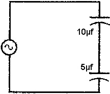 1. If two capacitors are connected
in series across a voltage source, the smaller one will charge up to the larger
proportion of the applied voltage. 1. If two capacitors are connected
in series across a voltage source, the smaller one will charge up to the larger
proportion of the applied voltage.
True _
False _
|
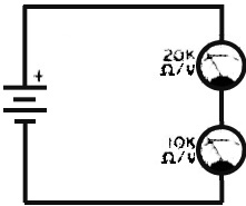 6. If two voltmeters, each set on the
same scale, are in series across a voltage source, the one with the higher ohms/volt
rating gives the greater deflection. 6. If two voltmeters, each set on the
same scale, are in series across a voltage source, the one with the higher ohms/volt
rating gives the greater deflection.
True _
False _
|
|
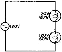 2. If two lamps of equal voltage and
wattage rating are connected in series across a power source, each will deliver
one-half of its rated power. 2. If two lamps of equal voltage and
wattage rating are connected in series across a power source, each will deliver
one-half of its rated power.
True _
False _
|
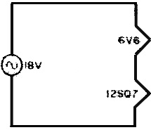 7. If the filaments of a 6V6 and a
12SQ7 electron tube are wired in series, the tubes will operate satisfactorily when
connected across an 18-volt source. 7. If the filaments of a 6V6 and a
12SQ7 electron tube are wired in series, the tubes will operate satisfactorily when
connected across an 18-volt source.
True _
False _
|
|
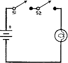 3. If two s.p.s.t. switches are connected
in series with a battery and a lamp. the arrangement may be considered the same
as an "OR" logic circuit. 3. If two s.p.s.t. switches are connected
in series with a battery and a lamp. the arrangement may be considered the same
as an "OR" logic circuit.
True _
False _
|
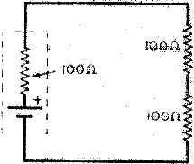 8. Two 100-ohm resistors placed across
a battery having an internal resistance of 100 ohms dissipate twice as much power
as one of the external resistors. 8. Two 100-ohm resistors placed across
a battery having an internal resistance of 100 ohms dissipate twice as much power
as one of the external resistors.
True -.
False _
|
|
 4. If a 3-ohm, 2-watt speaker and a
6-ohm, 1-watt speaker are connected in series, the 1-watt speaker will deliver twice
as much power as the 2-watt speaker . 4. If a 3-ohm, 2-watt speaker and a
6-ohm, 1-watt speaker are connected in series, the 1-watt speaker will deliver twice
as much power as the 2-watt speaker .
True _
False _
|
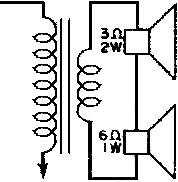
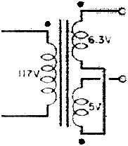 9. If the two secondary windings of
a transformer are in series as shown, the output voltage is the sum of the individual
secondary coil voltages. 9. If the two secondary windings of
a transformer are in series as shown, the output voltage is the sum of the individual
secondary coil voltages.
True _
False _
|
|
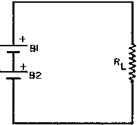 5. If two dry cells of equal current
and voltage rating are connected in series across a load, the current-handling capability
of the circuit is increased twofold. 5. If two dry cells of equal current
and voltage rating are connected in series across a load, the current-handling capability
of the circuit is increased twofold.
True _
False _
|
 10. If a 500-ohm. 5-watt resistor and
a 500-ohm, 10-watt resistor are in series across a 100-volt source, they are considered
equal to a 1000-ohm, 15-watter. 10. If a 500-ohm. 5-watt resistor and
a 500-ohm, 10-watt resistor are in series across a 100-volt source, they are considered
equal to a 1000-ohm, 15-watter.
True _
False _
|
See answers below.
Quizzes from vintage electronics magazines such as Popular
Electronics, Electronics-World, QST, and Radio News
were published over the years - some really simple and others not so simple. Robert P. Balin
created most of the quizzes for Popular Electronics. This is a listing
of all I have posted thus far.
- RF Cafe Quiz #71:
Tech Headlines for Week of 3/13/2023
- RF Cafe Quiz #70:
Analog &
RF Filter Basics
- RF Cafe Quiz #69:
RF
Electronics Basics
- RF Cafe Quiz #68:
RF & Analog Company Mergers & Acquisitions in 2017
- RF Cafe Quiz #67:
RF & Microwave Company Name Change History
- RF Cafe Quiz #66:
Spectrum and Network Measurements
- RF Cafe Quiz #65:
Troubleshooting & Repairing Commercial Electrical Equipment
- RF Cafe Quiz #64:
Space-Time Adaptive Processing for Radar
- RF Cafe Quiz #63:
Envelope Tracking Power Amplifiers
- RF Cafe Quiz #62:
Stimson's Introduction to Airborne Radar
- RF Cafe Quiz #61:
Practical Microwave Circuits
- RF Cafe Quiz #60:
Ten Essential Skills for Electrical Engineers
- RF Cafe Quiz #59:
Microwave Circulator Design
- RF Cafe Quiz #58:
Microwave and Millimeter-Wave Electronic Packaging
- RF Cafe Quiz #57:
Frequency-Agile Antennas for Wireless Communications
- RF Cafe Quiz #56:
Tube Testers
and Electron Tube Equipment
- RF Cafe Quiz #55:
Conquer
Radio Frequency
- RF Cafe Quiz #54:
Microwave Mixer Technology and Applications
- RF Cafe Quiz #53:
Chipless RFID Reader Architecture
- RF Cafe Quiz #52:
RF and Microwave Power Amplifiers
- RF Cafe Quiz #51:
Antennas and Site Engineering for Mobile Radio Networks
- RF Cafe Quiz #50:
Microstrip Lines and Slotlines
- RF Cafe Quiz #49:
High-Frequency Integrated Circuits
- RF Cafe Quiz #48:
Introduction to Infrared and Electro-Optical Systems
- RF Cafe Quiz #47:
LCP for Microwave Packages and Modules
- RF Cafe Quiz #46:
RF, Microwave, and Millimeter-Wave Components
- RF Cafe Quiz #45:
Dielectric and Thermal Properties of Materials at Microwave Frequencies
- RF Cafe Quiz #44:
Monopulse Principles and Techniques
- RF Cafe Quiz #43:
Plasma Antennas
- RF Cafe Quiz #42: The Micro-Doppler
Effect in Radar
- RF Cafe Quiz #41: Introduction
to RF Design Using EM Simulators
- RF Cafe Quiz #40: Introduction
to Antenna Analysis Using EM Simulation
- RF Cafe Quiz #39: Emerging
Wireless Technologies and the Future Mobile Internet
- RF Cafe Quiz #38: Klystrons,
Traveling Wave Tubes, Magnetrons, Crossed-Field Amplifiers, and Gyrotrons
- RF Cafe Quiz #37: Component
Reliability for Electronic Systems
- RF Cafe Quiz #36: Advanced
RF MEMS
- RF Cafe Quiz #35: Frequency
Synthesizers: Concept to Product
- RF Cafe Quiz #34: Multi-Gigabit
Microwave and Millimeter-Wave Wireless Communications
- RF Cafe Quiz #33: Battlespace
Technologies: Network-Enabled Information Dominance
- RF Cafe Quiz #32: Modern Communications
Receiver Design and Technology
- RF Cafe Quiz #31: Quantum
Mechanics of Nanostructures
- RF Cafe Quiz #30: OFDMA System
Analysis and Design
- RF Cafe Quiz #29: Cognitive
Radar
- RF Cafe Quiz #28: Human-Centered
Information Fusion
- RF Cafe Quiz #27: Remarkable
Engineers
- RF Cafe Quiz #26: Substrate
Noise Coupling in Analog/RF Circuits
- RF Cafe Quiz #25: Component
Reliability for Electronic Systems
- RF Cafe Quiz #24: Ultra Low
Power Bioelectronics
- RF Cafe Quiz #23: Digital
Communications Basics
- RF Cafe Quiz #22: Remember
the Basics?
- RF Cafe Quiz #21: Wireless
Standards Knowledge
- RF Cafe Quiz #20: Famous First
Names
- RF Cafe Quiz #19: Basic Circuit
Theory
- RF Cafe Quiz #18: Archaic
Scientific Words & Definitions
- RF Cafe Quiz #17: Inventors &
Their Inventions
- RF Cafe Quiz #16: Antennas
- RF Cafe Quiz #15: Numerical
Constants
- RF Cafe Quiz #14: Oscillators
- RF Cafe Quiz #13: General
Knowledge
- RF Cafe Quiz #12: Electronics
Corporations Headquarters
- RF Cafe Quiz #11: Famous Inventors &
Scientists
- RF Cafe Quiz #10: A Sampling
of RF & Wireless Topics
- RF Cafe Quiz #9: A Smorgasbord
of RF Topics
- RF Cafe Quiz #8: Hallmark Decades
in Electronics
- RF Cafe Quiz #7: Radar Fundamentals
- RF Cafe Quiz #6: Wireless Communications
Fundamentals
- RF Cafe Quiz #5: Company Logo
Recognition
- RF Cafe Quiz #4: General RF
Topics
- RF Cafe Quiz #3: General RF/Microwave
Topics
- RF Cafe Quiz #2: General RF
Topics
- RF Cafe Quiz #1: General RF
Knowledge
- Vacuum Tube Quiz,
February 1961 Popular Electronics
- Kool-Keeping Kwiz, June
1970 Popular Electronics
- Find the Brightest
Bulb Quiz, April 1960 Popular Electronics
-
Where Do the Scientists Belong? - Feb 19, 1949 Saturday Evening Post
|
-
What's Your EQ? - April 1967 Radio-Electronics
-
What's Your EQ? -
March 1967 Radio-Electronics
-
What's Your EQ? - December 1964 Radio-Electronics
-
What's Your EQ? - January 1967 Radio-Electronics
-
Wanted: 50,000 Engineers - January 1953 Popular Mechanics
-
What's Your EQ? - August 1964 Radio-Electronics
- Voltage Quiz
- December 1961 Popular Electronics
-
What is It? - June 1941 Popular Science
- What Do You Know
About Resistors? - April 1974 Popular Electronics
-
What's Your EQ? - September 1963 Radio-Electronics
- Potentiometer Quiz - September
1962 Popular Electronics
-
Mathematical Bafflers - March 1965 Mechanix Illustrated
- Op Amp Quiz -
October 1968 Popular Electronics
- Electronic "A"
Quiz - April 1968 Popular Electronics
-
What's Your EQ? - May 1961 Radio-Electronics
-
Popular Science Question Bee - February 1939 Popular Science
-
What is It? - A Question Bee in Photographs - June 1941 Popular Science
-
What's Your EQ? - June 1961 Radio-Electronics
-
What's Your EQ? - June 1964 Radio-Electronics
-
What's Your EQ? - May 1964 Radio-Electronics
-
What's Your EQ? - August 1963 Radio-Electronics
-
What's Your EQ? - May 1963 Radio-Electronics
- Bridge
Function Quiz - September 1969 Radio-Electronics
-
What's Your EQ? - March 1963 Radio-Electronics
-
What's Your EQ? - February 1967 Radio-Electronics
-
Circuit Quiz - June 1966 Radio-Electronics
-
What's Your EQ? - June 1966 Radio-Electronics
- Electronics
Mathematics Quiz - June 1969 Popular Electronics
- Brightest
Light Quiz - April 1964 Popular Electronics
-
What's Your EQ? - April 1963 Radio-Electronics
- Electronics "B" Quiz
- July 1969 Popular Electronics
- Ohm's Law Quiz
- March 1969 Popular Electronics
-
Antenna Quiz - November 1962 Electronics World
- Color Code Quiz
- November 1967 Popular Electronics
- CapaciQuiz
- August 1961 Popular Electronics
- Transformer
Winding Quiz - December 1964 Popular Electronics
-
Audiophile Quiz - November 1957 Radio-electronics
- Capacitor
Function Quiz - March 1962 Popular Electronics
- Greek Alphabet
Quiz - December 1963 Popular Electronics
- Circuit
Designer's Name Quiz - July 19680 Popular Electronics
-
Sawtooth Sticklers Quiz - November 1960 Radio-Electronics
-
Elementary
Radio Quiz - December 1947 Radio-Craft
- Hi-Fi
Quiz - October 1955 Radio & Television News
- Electronics Physics
Quiz - March 1974 Popular Electronics
- A Baffling Quiz
- January 1968 Popular Electronics
- Electronics IQ
Quiz - May 1967 Popular Electronics
- Plug and Jack
Quiz - December 1967 Popular Electronics
- Electronic
Switching Quiz - October 1967 Popular Electronics
- Electronic
Angle Quiz - September 1967 Popular Electronics
- International
Electronics Quiz - July 1967 Popular Electronics
- FM Radio
Quiz - April 1950 Radio & Television News
- Bridge Circuit
Quiz -December 1966 Popular Electronics
- Diode Function
Quiz - August 1965 Popular Electronics
- Diagram Quiz,
August 1966 Popular Electronics
- Quist Quiz - November
1953 QST
- TV Trouble Quiz,
July 1966 Popular Electronics
- Electronics History Quiz,
December 1965 Popular Electronics
- Scope-Trace Quiz,
March 1965 Popular Electronics
-
Electronic
Circuit Analogy Quiz, April 1973
-
Test Your Knowledge of Semiconductors, August 1972 Popular Electronics
- Ganged Switching
Quiz, April 1972 Popular Electronics
- Lamp Brightness
Quiz, January 1969 Popular Electronics
- Lissajous
Pattern Quiz, September 1963 Popular Electronics
- Electronic
Quizoo, October 1962 Popular Electronics
- Electronic
Photo Album Quiz, March 1963 Popular Electronics
- Electronic
Alphabet Quiz, May 1963 Popular Electronics
- Quiz: Resistive?
Inductive? or Capacitive?, October 1960 Popular Electronics
- Vector-Circuit
Matching Quiz, June 1970 Popular Electronics
- Inductance
Quiz, September 1961 Popular Electronics
- RC Circuit Quiz,
June 1963 Popular Electronics
- Diode Quiz, July
1961 Popular Electronics
- Electronic
Curves Quiz, February 1963 Popular Electronics
- Electronic
Numbers Quiz, December 1962 Popular Electronics
- Energy Conversion
Quiz, April 1963 Popular Electronics
- Coil Function
Quiz, June 1962 Popular Electronics
-
Co-Inventors Quiz - January 1965 Electronics World
-
"-Tron" Teasers Quiz - October 1963 Electronics World
- Polarity Quiz
- March 1968 Popular Electronics
-
Television
I.Q. Quiz - October 1948 Radio & Television News
- Amplifier Quiz
Part I - February 1964 Popular Electronics
- Semiconductor
Quiz - February 1967 Popular Electronics
- Unknown
Frequency Quiz - September 1965 Popular Electronics
- Electronics
Metals Quiz - October 1964 Popular Electronics
- Electronics
Measurement Quiz - August 1967 Popular Electronics
- Meter-Reading
Quiz, June 1966 Popular Electronics
- Electronic
Geometry Quiz, January 1965 Popular Electronics
- Electronic
Factor Quiz, November 1966 Popular Electronics
- Electronics
Math Quiz, November 1965 Popular Electronics
- Series Circuit
Quiz, May 1966 Popular Electronics
- Electrochemistry
Quiz, March 1966 Popular Electronics
- Biz
Quiz: Test Your Sales Ability - April 1947 Radio News
- Electronic
Analogy Quiz, November 1961 Popular Electronics
- Electronic
Coupling Quiz, August 1973 Popular Electronics
- Electronics
Analogy Quiz, August 1960 Popular Electronics
- Audio Quiz, April
1955 Popular Electronics
- Electronic Unit
Quiz, May 1962 Popular Electronics
- Capacitor
Circuit Quiz, June 1968 Popular Electronics
|
Quiz Answers
1. True. With unequal capacitors in series, the voltage across each capacitor
is inversely proportional to its capacitance. This is shown by the formula E = Q/C,
where Q, the number of electrons moving in the circuit, is the same for both capacitors.
2. False. Since the lamps have the same resistance, the applied voltage and the
current in the circuit will be reduced by a factor of one-half. And, since P = EI,
each lamp will operate at one-fourth its rated power.
3. False. As shown, S1 and S2 must both be closed before the lamp will light,
so that the arrangement forms an "AND" circuit.
4. True. Each speaker will receive the same amount of current from the source,
and, since P = I2Z, the power developed will be a function of the voice
coil impedance, Z. The 6-ohm speaker produces twice the power of the 3-ohm speaker
for the same input.
5. False. Although the total voltage across the two cells in series equals the
sum of the individual cell voltage, like two similar fuses in series, the current-handling
capability of the circuit is not altered.
6. True. Voltmeter sensitivity is a product of its ohms/volt rating and the scale
setting. On the 5-volt scale, the resistance of the 20,000 ohms/volt meter is 100,000
ohms, while the resistance of the 10,000 ohms/ volt meter is 50,000 ohms. The voltage
drop across the 20,000 ohms/volt meter is greater than the drop across the other
meter, giving a greater deflection.
7. False. From the tube manual, a 6V6 draws 450 ma, while a 12SQ7 draws only
150 ma. From Ohm's law, the filament resistances are, respectively, 13 ohms and
80 ohms. Therefore, the current in the series circuit would be approximately 200
ma., placing 2.6 volts across the 6V6, and more than 15 volts across the 12SQ7.
8. False. Since P = I2R, the reduced current resulting from two resistors
instead of one has a greater effect on the power dissipation than does an increase
in resistance.
9. True. The polarity marks indicate that the secondary voltages are in phase
and are series-aiding. Thus, the output voltage is the sum of the two secondary
voltages.
10. False. Since a current of 100 ma. flows in the circuit, the power dissipated
by each resistor is 5 watts (P = EI) for a total dissipation of 10 watts. If a 1000-ohm
resistor is substituted for the two 500-ohm units, the power dissipation remains
at 10 watts (by the same formula).
Posted April 27, 2022
(updated from original post on 4/9/ 2016)
|


