|
October 1969 Popular Electronics
 Table of Contents Table of Contents
Wax nostalgic about and learn from the history of early electronics. See articles
from
Popular Electronics,
published October 1954 - April 1985. All copyrights are hereby acknowledged.
|
Here is an 10-question quiz on the basics of operational amplifiers (aka op amps,
or opamps, compliments of Mr. John Seginski, in the October 1969 issue of
Popular Electronics magazine. The first commercial opamp, the
μA709,
was introduced by Fairchild Semiconductor in 1963 (designed by Bob Widlar). Five
years later they released the
μA741,
which was the most famous opamp of the era; it is still widely used today. One of
my electronics circuit courses in college (c1987) used the 741 as the basis for
analyzing integrated circuits, and in particular, opamps. A couple companies offered
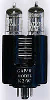
vacuum tube operational amplifiers which combined two or more tubes along with some
integrated leaded biasing and compensating components, and had a tube sock pinout
on the bottom for plugging into a standard socket. The
GAP/R K2-W, produced by George A. Philbrick
Researches (hence the GAP/R prefix), shown at the left is an example. It was commonly
advertised in electronics magazines of the era. Today, just about everyone having
any involvement knows the basic equations for calculating opamp gain for both inverting
(Rfeedback/Rinput) and non-inverting (Rfeedback/Rgnd
+1) configurations.
Op Amp Quiz
 By John Seginski By John Seginski
That versatile building block, the operational amplifier, is the mindspring of
much of today's most advanced electronic equipment. In computers and automatic control
systems, for example, they are indispensable, and they can be made to function in
a number of different ways - precision voltage sources, current sources, and voltage
adders, to name only a few.
The operational amplifier, or op amp, is an extremely high -gain amplifier with
a very high input impedance. The actual gain of a specific circuit is determined
by feedback resistors connected around the amplifier. Various characteristics can
be achieved is generated. by connecting other components and other op amps in the
circuit. The numbered sentences and equations that follow refer to the circuits
below. Test your knowledge of op amps by filling in the blanks.
1. Eout = ______
2. Gain = ______
3. Eout = ______
4. This is a ______ generator.
5. Gain = ______
6. This is a ______ voltage amplifier.
7. This is an ______
8. This is a ______
9. When switches are closed one by one, ______ are generated.
10. The outputs are ______.
See answers below.
Quizzes from vintage electronics magazines such as Popular
Electronics, Electronics-World, QST, and Radio News
were published over the years - some really simple and others not so simple. Robert P. Balin
created most of the quizzes for Popular Electronics. This is a listing
of all I have posted thus far.
- RF Cafe Quiz #71:
Tech Headlines for Week of 3/13/2023
- RF Cafe Quiz #70:
Analog &
RF Filter Basics
- RF Cafe Quiz #69:
RF
Electronics Basics
- RF Cafe Quiz #68:
RF & Analog Company Mergers & Acquisitions in 2017
- RF Cafe Quiz #67:
RF & Microwave Company Name Change History
- RF Cafe Quiz #66:
Spectrum and Network Measurements
- RF Cafe Quiz #65:
Troubleshooting & Repairing Commercial Electrical Equipment
- RF Cafe Quiz #64:
Space-Time Adaptive Processing for Radar
- RF Cafe Quiz #63:
Envelope Tracking Power Amplifiers
- RF Cafe Quiz #62:
Stimson's Introduction to Airborne Radar
- RF Cafe Quiz #61:
Practical Microwave Circuits
- RF Cafe Quiz #60:
Ten Essential Skills for Electrical Engineers
- RF Cafe Quiz #59:
Microwave Circulator Design
- RF Cafe Quiz #58:
Microwave and Millimeter-Wave Electronic Packaging
- RF Cafe Quiz #57:
Frequency-Agile Antennas for Wireless Communications
- RF Cafe Quiz #56:
Tube Testers
and Electron Tube Equipment
- RF Cafe Quiz #55:
Conquer
Radio Frequency
- RF Cafe Quiz #54:
Microwave Mixer Technology and Applications
- RF Cafe Quiz #53:
Chipless RFID Reader Architecture
- RF Cafe Quiz #52:
RF and Microwave Power Amplifiers
- RF Cafe Quiz #51:
Antennas and Site Engineering for Mobile Radio Networks
- RF Cafe Quiz #50:
Microstrip Lines and Slotlines
- RF Cafe Quiz #49:
High-Frequency Integrated Circuits
- RF Cafe Quiz #48:
Introduction to Infrared and Electro-Optical Systems
- RF Cafe Quiz #47:
LCP for Microwave Packages and Modules
- RF Cafe Quiz #46:
RF, Microwave, and Millimeter-Wave Components
- RF Cafe Quiz #45:
Dielectric and Thermal Properties of Materials at Microwave Frequencies
- RF Cafe Quiz #44:
Monopulse Principles and Techniques
- RF Cafe Quiz #43:
Plasma Antennas
- RF Cafe Quiz #42: The Micro-Doppler
Effect in Radar
- RF Cafe Quiz #41: Introduction
to RF Design Using EM Simulators
- RF Cafe Quiz #40: Introduction
to Antenna Analysis Using EM Simulation
- RF Cafe Quiz #39: Emerging
Wireless Technologies and the Future Mobile Internet
- RF Cafe Quiz #38: Klystrons,
Traveling Wave Tubes, Magnetrons, Crossed-Field Amplifiers, and Gyrotrons
- RF Cafe Quiz #37: Component
Reliability for Electronic Systems
- RF Cafe Quiz #36: Advanced
RF MEMS
- RF Cafe Quiz #35: Frequency
Synthesizers: Concept to Product
- RF Cafe Quiz #34: Multi-Gigabit
Microwave and Millimeter-Wave Wireless Communications
- RF Cafe Quiz #33: Battlespace
Technologies: Network-Enabled Information Dominance
- RF Cafe Quiz #32: Modern Communications
Receiver Design and Technology
- RF Cafe Quiz #31: Quantum
Mechanics of Nanostructures
- RF Cafe Quiz #30: OFDMA System
Analysis and Design
- RF Cafe Quiz #29: Cognitive
Radar
- RF Cafe Quiz #28: Human-Centered
Information Fusion
- RF Cafe Quiz #27: Remarkable
Engineers
- RF Cafe Quiz #26: Substrate
Noise Coupling in Analog/RF Circuits
- RF Cafe Quiz #25: Component
Reliability for Electronic Systems
- RF Cafe Quiz #24: Ultra Low
Power Bioelectronics
- RF Cafe Quiz #23: Digital
Communications Basics
- RF Cafe Quiz #22: Remember
the Basics?
- RF Cafe Quiz #21: Wireless
Standards Knowledge
- RF Cafe Quiz #20: Famous First
Names
- RF Cafe Quiz #19: Basic Circuit
Theory
- RF Cafe Quiz #18: Archaic
Scientific Words & Definitions
- RF Cafe Quiz #17: Inventors &
Their Inventions
- RF Cafe Quiz #16: Antennas
- RF Cafe Quiz #15: Numerical
Constants
- RF Cafe Quiz #14: Oscillators
- RF Cafe Quiz #13: General
Knowledge
- RF Cafe Quiz #12: Electronics
Corporations Headquarters
- RF Cafe Quiz #11: Famous Inventors &
Scientists
- RF Cafe Quiz #10: A Sampling
of RF & Wireless Topics
- RF Cafe Quiz #9: A Smorgasbord
of RF Topics
- RF Cafe Quiz #8: Hallmark Decades
in Electronics
- RF Cafe Quiz #7: Radar Fundamentals
- RF Cafe Quiz #6: Wireless Communications
Fundamentals
- RF Cafe Quiz #5: Company Logo
Recognition
- RF Cafe Quiz #4: General RF
Topics
- RF Cafe Quiz #3: General RF/Microwave
Topics
- RF Cafe Quiz #2: General RF
Topics
- RF Cafe Quiz #1: General RF
Knowledge
- Vacuum Tube Quiz,
February 1961 Popular Electronics
- Kool-Keeping Kwiz, June
1970 Popular Electronics
- Find the Brightest
Bulb Quiz, April 1960 Popular Electronics
-
Where Do the Scientists Belong? - Feb 19, 1949 Saturday Evening Post
|
-
What's Your EQ? - April 1967 Radio-Electronics
-
What's Your EQ? -
March 1967 Radio-Electronics
-
What's Your EQ? - December 1964 Radio-Electronics
-
What's Your EQ? - January 1967 Radio-Electronics
-
Wanted: 50,000 Engineers - January 1953 Popular Mechanics
-
What's Your EQ? - August 1964 Radio-Electronics
- Voltage Quiz
- December 1961 Popular Electronics
-
What is It? - June 1941 Popular Science
- What Do You Know
About Resistors? - April 1974 Popular Electronics
-
What's Your EQ? - September 1963 Radio-Electronics
- Potentiometer Quiz - September
1962 Popular Electronics
-
Mathematical Bafflers - March 1965 Mechanix Illustrated
- Op Amp Quiz -
October 1968 Popular Electronics
- Electronic "A"
Quiz - April 1968 Popular Electronics
-
What's Your EQ? - May 1961 Radio-Electronics
-
Popular Science Question Bee - February 1939 Popular Science
-
What is It? - A Question Bee in Photographs - June 1941 Popular Science
-
What's Your EQ? - June 1961 Radio-Electronics
-
What's Your EQ? - June 1964 Radio-Electronics
-
What's Your EQ? - May 1964 Radio-Electronics
-
What's Your EQ? - August 1963 Radio-Electronics
-
What's Your EQ? - May 1963 Radio-Electronics
- Bridge
Function Quiz - September 1969 Radio-Electronics
-
What's Your EQ? - March 1963 Radio-Electronics
-
What's Your EQ? - February 1967 Radio-Electronics
-
Circuit Quiz - June 1966 Radio-Electronics
-
What's Your EQ? - June 1966 Radio-Electronics
- Electronics
Mathematics Quiz - June 1969 Popular Electronics
- Brightest
Light Quiz - April 1964 Popular Electronics
-
What's Your EQ? - April 1963 Radio-Electronics
- Electronics "B" Quiz
- July 1969 Popular Electronics
- Ohm's Law Quiz
- March 1969 Popular Electronics
-
Antenna Quiz - November 1962 Electronics World
- Color Code Quiz
- November 1967 Popular Electronics
- CapaciQuiz
- August 1961 Popular Electronics
- Transformer
Winding Quiz - December 1964 Popular Electronics
-
Audiophile Quiz - November 1957 Radio-electronics
- Capacitor
Function Quiz - March 1962 Popular Electronics
- Greek Alphabet
Quiz - December 1963 Popular Electronics
- Circuit
Designer's Name Quiz - July 19680 Popular Electronics
-
Sawtooth Sticklers Quiz - November 1960 Radio-Electronics
-
Elementary
Radio Quiz - December 1947 Radio-Craft
- Hi-Fi
Quiz - October 1955 Radio & Television News
- Electronics Physics
Quiz - March 1974 Popular Electronics
- A Baffling Quiz
- January 1968 Popular Electronics
- Electronics IQ
Quiz - May 1967 Popular Electronics
- Plug and Jack
Quiz - December 1967 Popular Electronics
- Electronic
Switching Quiz - October 1967 Popular Electronics
- Electronic
Angle Quiz - September 1967 Popular Electronics
- International
Electronics Quiz - July 1967 Popular Electronics
- FM Radio
Quiz - April 1950 Radio & Television News
- Bridge Circuit
Quiz -December 1966 Popular Electronics
- Diode Function
Quiz - August 1965 Popular Electronics
- Diagram Quiz,
August 1966 Popular Electronics
- Quist Quiz - November
1953 QST
- TV Trouble Quiz,
July 1966 Popular Electronics
- Electronics History Quiz,
December 1965 Popular Electronics
- Scope-Trace Quiz,
March 1965 Popular Electronics
-
Electronic
Circuit Analogy Quiz, April 1973
-
Test Your Knowledge of Semiconductors, August 1972 Popular Electronics
- Ganged Switching
Quiz, April 1972 Popular Electronics
- Lamp Brightness
Quiz, January 1969 Popular Electronics
- Lissajous
Pattern Quiz, September 1963 Popular Electronics
- Electronic
Quizoo, October 1962 Popular Electronics
- Electronic
Photo Album Quiz, March 1963 Popular Electronics
- Electronic
Alphabet Quiz, May 1963 Popular Electronics
- Quiz: Resistive?
Inductive? or Capacitive?, October 1960 Popular Electronics
- Vector-Circuit
Matching Quiz, June 1970 Popular Electronics
- Inductance
Quiz, September 1961 Popular Electronics
- RC Circuit Quiz,
June 1963 Popular Electronics
- Diode Quiz, July
1961 Popular Electronics
- Electronic
Curves Quiz, February 1963 Popular Electronics
- Electronic
Numbers Quiz, December 1962 Popular Electronics
- Energy Conversion
Quiz, April 1963 Popular Electronics
- Coil Function
Quiz, June 1962 Popular Electronics
-
Co-Inventors Quiz - January 1965 Electronics World
-
"-Tron" Teasers Quiz - October 1963 Electronics World
- Polarity Quiz
- March 1968 Popular Electronics
-
Television
I.Q. Quiz - October 1948 Radio & Television News
- Amplifier Quiz
Part I - February 1964 Popular Electronics
- Semiconductor
Quiz - February 1967 Popular Electronics
- Unknown
Frequency Quiz - September 1965 Popular Electronics
- Electronics
Metals Quiz - October 1964 Popular Electronics
- Electronics
Measurement Quiz - August 1967 Popular Electronics
- Meter-Reading
Quiz, June 1966 Popular Electronics
- Electronic
Geometry Quiz, January 1965 Popular Electronics
- Electronic
Factor Quiz, November 1966 Popular Electronics
- Electronics
Math Quiz, November 1965 Popular Electronics
- Series Circuit
Quiz, May 1966 Popular Electronics
- Electrochemistry
Quiz, March 1966 Popular Electronics
- Biz
Quiz: Test Your Sales Ability - April 1947 Radio News
- Electronic
Analogy Quiz, November 1961 Popular Electronics
- Electronic
Coupling Quiz, August 1973 Popular Electronics
- Electronics
Analogy Quiz, August 1960 Popular Electronics
- Audio Quiz, April
1955 Popular Electronics
- Electronic Unit
Quiz, May 1962 Popular Electronics
- Capacitor
Circuit Quiz, June 1968 Popular Electronics
|
Op Amp Quiz Answers
1. The gain of an operational amplifier as shown can be determined by dividing
the value of the feedback R1 by the value of the input resistor R15. Therefore the
gain of the circuit is 1000/500=2. Note that the input connects to the input terminal
marked (-) and the output connects to the output terminal marked (+). The circuit
is thus an inverting amplifier. Since the input is -5 volts, Ecl is +10 volts.
2. The gain of this inverting amplifier is also determined by dividing the feedback
resistance 'by the input resistance. Thus, gain=100/ 1000=0.1. Since the amplifier
inverts, the gain is actually -0.1.
3. Operational amplifiers can be used to "sum" or algebraically add the voltages
at their inputs. In this circuit, the gain of each input leg is one. The output
voltage is the sum of the amplified inputs and is inverted. Thus Eour is +6 volts.
4. Operational amplifiers can be used as current generators if the current in
the feedback loop is utilized. The load must be connected into the feedback loop
as shown in the circuit.
5. The gain of the voltage follower is one. The input impedance of this circuit
is very high and the output impedance is very low. The circuit is noninverting.
6. Notice that E15 connects to the input terminal marked (+) and EvT connects
to the output terminal marked (+). Therefore this is a non -inverting amplifier.
7. The circuit is an integrator because the effective output is that which appears
across the capacitor.
8. The circuit is a differentiator because the effective output is that which
appears across the resistor.
9. As the switches are closed one by one, the inputs are inverted and summed,
one on top of the other in sequence, generating a positive staircase waveform.
10. The first of these two unity -gain amplifiers inverts the input signal. The
second inverts the output of the first. Therefore, the outputs are balanced.
Posted September 25, 2023
|