|
November 1946 Radio News
 [Table
of Contents] [Table
of Contents]
Wax nostalgic about and learn from the history of early
electronics. See articles from
Radio & Television News, published 1919-1959. All copyrights hereby
acknowledged.
|
Selenium
rectifiers were the first widely used replacements for vacuum tubes in commercial
electronic equipment. Since amplification was not possible - that came in late 1948
with the invention of the
transistor, compliments of Shockley, Brattain and Bardeen - diode
action in AC-DC power supplies was its primary application. Typical reverse breakdown
voltage is in the neighborhood of 20 volts and current handling capability depends
on the interface surface area. Cost kept the selenium rectifiers from being widely
adapted early in their history (1933), but by 1946
when this article was published Radio-News magazine it had dropped enough to make their use economical.
Eliminating one or two vacuum tubes in a radio or television power supply made the
sets more efficient and increased reliability since the selenium rectifiers rarely
suffered failures if designed into the circuit correctly.
Electronics magazines of the era published many articles about selenium rectifiers,
including
After Class: Working with Selenium Rectifiers,
The Semiconductor Diode,
New Selenium Rectifiers for Home Receivers,
Selenium Rectifiers,
Applications of Small High-Voltage Selenium Rectifiers, and
Using
Selenium Rectifiers.
New Selenium Rectifiers for Home Receivers

Fig. 1 - Typical portable receiver used to illustrate
step-by-step installation of selenium rectifier.
By George Eannarino
Field Eng., Federal Telephone & Radio Corporation.
Selenium rectifiers have been designed to replace all conventional types of rectifier
tubes used in home receivers.
Markedly improving the performance of home receivers and completely trouble-free,
the new miniature selenium rectifier stack, developed by Federal Telephone and Radio
Corporation, Newark, N. J. means more "customer satisfaction" plus increased profits
to the up-to-the-minute serviceman. One of the first advancements made in home radios
since the end of the .war, this stack replaces all conventional rectifier tubes,
is simple to install, and is guaranteed to outlive the receiver, thereby ensuring
a minimum of power supply failures.
With competition in the service field mounting, this latest development should
provide a "shot in the arm" for many alert radio repairmen for it has such excellent
selling points, such as instantaneous starting for both a.c. and d.c., less heat,
longer battery life (in portables), improved tonal quality, trouble-free power supply
operation, pilot light failures reduced to a minimum, and more audio output (in
35Z5 circuits). In every case this new type of rectifier means customer satisfaction.
Selenium rectifiers have been used in electronic circuits for many years but
due to their relatively high cost and large space factor they were not used in home
receiver rectifier circuits. However, by virtue of a new process developed by Federal,
this cost and space factor has been reduced to the point where use of the miniature
selenium rectifier is entirely practical.
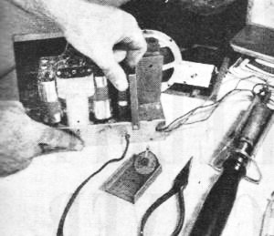
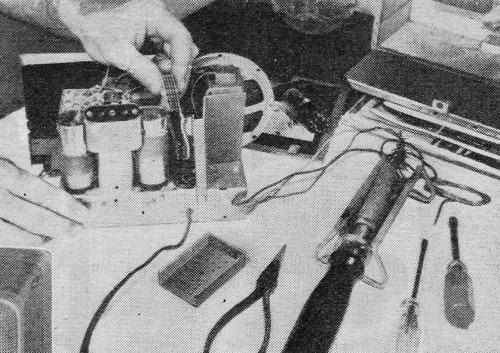
Fig. 2 - Chassis is withdrawn from cabinet and rectifier
tube removed. Only four tools are needed for complete conversion.

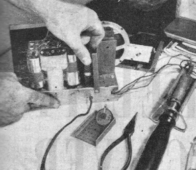
Fig. 3 - Two extension leads are soldered on the selenium
rectifier lugs. Positive side is shown by red wire, negative by yellow or black.

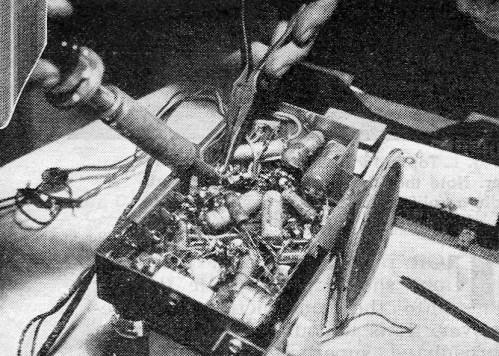
Fig. 4 - Here the leads are soldered on to the appropriate
pins. The red wire goes to pin 4 while yellow or black wire. whichever is used,
is soldered to pin 5.
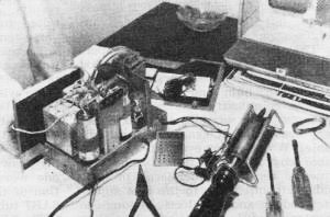
Fig. 5 - Rectifier operation should now be checked
by turning the receiver on. The set should operate immediately without the customary
warm-up period.

Fig. 6 - Final operation consists of tightening rectifier
to the chassis and placing shield over it. Chassis is then returned to the cabinet
with conversion completed.
The rectifier stack has two distinct poles, positive and negative, corresponding
to the plate and cathode of the vacuum tube and can be inserted into the circuit
as such. The positive side, denoted by a "+" sign, is equivalent to the cathode
while the negative side functions as the plate. Soldering the stack into the set
in this manner constitutes the entire replacement operation unless the filament
of the tube was linked to other parts of the circuit, in which case a resistor is
used to replace the rectifier tube filament.
Installation of the miniature #403D2625 selenium rectifier can be made right
in the customer's home as indicated in Figs. 1-6. The set shown is a typical three
powered portable using a 117Z6 rectifier. As is evident from the schematic of the
power supply (Fig. 7) the filament of this tube is not interlocked with any
other component in the set. Therefore it is only necessary to insert the stack into
the circuit along the lines outlined in the previous paragraph. Solder the positive
side to the cathode terminal on the tube socket, the negative side to the plate
terminal, and the installation is over.
Only four tools are required to perform the entire 7 minute operation, a soldering
iron, screw driver, socket wrench, and a pair of long nose pliers. First the chassis
is withdrawn from the cabinet and the tube is removed from the socket (Fig. 2).
Extension leads are then soldered on the rectifier stack. It is recommended that
the positive lead be covered with red wire so as to distinguish it from the negative
lead, which is usually made yellow or black (Fig. 3).
At this point it should be noted that, whenever possible, the stack should be
installed underneath the chassis. However, in this case, as is the case with many
portables, though the stack is only 1 1/4" x 1 1/4" x 11/16", it did not fit underneath
the chassis and was inserted from above in the space that was formerly occupied
by the tube. In this latter case some type of protective covering must be provided.
Fig. 4 shows the leads which were drawn through center of the tube socket
and soldered to the appropriate pins, the red lead to the cathode terminal and the
yellow one to the plate terminal. The set is then turned on and if the rectifier
has been installed correctly, it should start operating immediately, (Fig. 5).
Finally a protective covering, which is supplied with the rectifier, is placed around
the stack and tightened to the chassis via a screw and nut (Fig. 6), The chassis
is then put back in cabinet and the job is done.
After insulation of the rectifier, check filament voltage. If this is too high
for normal tube operation, insert a 27 ohm resistor in the line just before the
rectifier to bring the operating voltage of the filament back to normal.
Three operational improvements have been achieved with the installation of this
rectifier. In the first place, since rectification is now immediate, the set operates
as soon as it is turned on, in contrast to the filament warm-up period previously
required. Secondly, in view of the low internal impedance and high efficiency of
the stack, the ambient temperature of the set is reduced by approximately 35°
F. which results in increased battery life. Finally, the long life of the selenium
rectifier means that power supply troubles are reduced to a minimum.
Federal has developed replacement sheets covering every possible power supply
used in home receivers, which give specific, easy-to-follow instructions, on what
steps are necessary to install this rectifier. These sheets are available to all
servicemen and can be obtained by writing to Federal Telephone and Radio Corporation,
200 Mt. Pleasant Ave., Newark, N. J.

Fig. 7 - Schematic diagram shows method of substituting a
selenium rectifier for a conventional 117Z6 tube.
Posted July 1, 2022
(updated from original post on
10/30/2014)
|