After Class: Working with Selenium Rectifiers
|
|||
Per Wikipedia, "A selenium rectifier is a type of metal rectifier, invented in 1933. They were used to replace vacuum tube rectifiers in power supplies for electronic equipment, and in high current battery charger applications. The photoelectric and rectifying properties of selenium were observed by C. E. Fitts around 1886 but practical rectifier devices were not manufactured routinely until the 1930s. Compared with the earlier copper oxide rectifier, the selenium cell could withstand higher voltage but at a lower current capacity per unit area." Safety note from RF Cafe visitor Joe B.: Selenium dust is toxic. An MSDS sheet for selenium on a WV government website lists it as life threatening. Selenium is another one of those elements/compounds that are essential for life, but can kill you in too large of a quantity (like water). Electronics magazines of the era published many articles about selenium rectifiers, including After Class: Working with Selenium Rectifiers, The Semiconductor Diode, New Selenium Rectifiers for Home Receivers, Selenium Rectifiers, Applications of Small High-Voltage Selenium Rectifiers, and Using Selenium Rectifiers. After Class: Working with Selenium Rectifiers
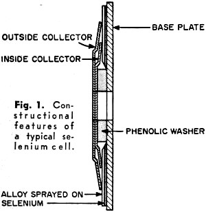
Fig. 1 - Constructional features of a typical selenium cell.
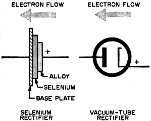
Fig. 2 - Selenium rectifier compared to a vacuum tube. The forward direction in the selenium is from alloy to baseplate. Thus, the alloy is comparable to the cathode and the baseplate to the plate of a vacuum-tube rectifier.
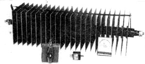
This photo shows a large 5-amp. selenium rectifier compared in size with a 500-ma. unit (left), a 50-ma. unit (center), and a common matchbox cover (right).
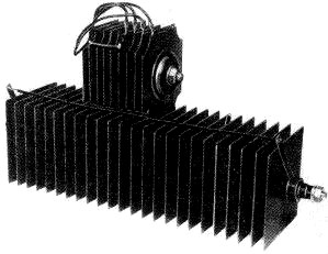
Resting on top of a modern selenium of the power variety is an old-type copper oxide rectifier. Although almost three times the size of the copper oxide unit, the selenium weighs less. Both can handle 5 amperes, but the selenium is rated at a five-times higher voltage, hence the extra length.
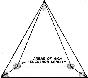
Fig. 3 - Electron charge density is always greatest at the points of greatest curvature. Here, density is highest at corners of pyramid.
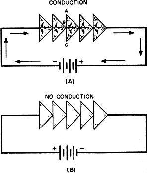
Fig. 4 - Forward or conductive direction (A) is from point to base of end-to-end crystals. High resistance direction (B) is opposite.
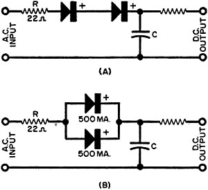
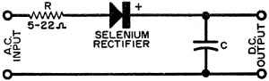
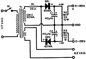
Fig. 5 - Selenium rectifiers in series (A) and in parallel (B) for increasing voltage and current handling capabilities, respectively. Special Information on Radio, TV, Radar and Nucleonics Working with Selenium Rectifiers Selenium rectifiers have long been accepted as an efficient means of converting a.c. to d.c. in industrial applications with relatively large power requirements. Their use has recently been expanded to include radio and TV receivers as well as all types of electronic control gear and mobile equipment. But although many millions of these units are now being employed, most experimenters are dangerously ignorant of their characteristics and limitations. "To know it well is to use it wisely" may be a highly questionable aphorism in many ways but it fits the selenium rectifier like the proverbial glove. Figure 1 is a cross section of a finished selenium cell. The etched-aluminum baseplate serves as the negative electrode and the low-temperature alloy as the positive electrode. In operation, electrons flow readily from the alloy to the baseplate but encounter high resistance in the opposite direction. The alloy plating behaves like the cathode of a vacuum tube and the aluminum baseplate serves as the anode or plate, with the selenium crystal layer actually performing the rectifying action (Fig. 2). Rectifying Action. During the manufacturing process, much care must be taken in the deposition of the metallic selenium on the baseplate, because performance of the finished rectifier depends upon the orientation of the individual crystals in the "barrier layer," as the selenium coating is called. Although the rectifying action is still imperfectly understood, the need for correct orientation suggests the following explanation. Consider a single crystal having a shape like that of a pyramid (Fig. 3). All metals contain many free electrons or carriers which distribute themselves according to certain well-known laws of electrostatics. One of these laws states that electric charges will concentrate on surfaces with the sharpest curvature; this is called the effect of points. As the sharpest curvatures on the surface of a pyramid are found at the corners, we should expect to find free electron density highest at these points. A potential applied to a line of crystals of this shape oriented end-to-end mayor may not cause a current to flow, depending upon the polarity of the voltage. When the direction of the e.m.f. is such as to move the electrons from a corner to a face (Fig. 4A), the carriers readily cross the interfacial boundary at B, moving into face AC, and thence distributing themselves at the corners. This is the forward or conduction direction. When the polarity of the voltage is reversed (Fig. 4B), the deficiency of electrons on the flat faces limits the number of carriers, conduction does not occur readily, and the resistance is substantially higher. If we now replace the batteries with an a.c. source, the conduction is essentially unidirectional and rectification takes place. Voltage and Current Ratings. Seleniums are available in an almost unlimited range of voltages and currents. Those popular for radio and TV applications may be roughly limited to a maximum r.m.s. voltage input of 130 volts and a current range from 50 ma. to 600 ma. d.c. Such seleniums are designed to operate at a.c. line voltage, i.e., about 120 volts r.m.s. Note, however, that even a 500-ma. rectifier is capable of carrying more than twice the current of the largest receiving type rectifier, the 5U4G. In the real power sizes -5 ampere capacity and more-selenium rectifiers are no less bulky than other types but they weigh considerably less. The selenium ratings given above carry two distinct warnings: do not exceed the rated current for any extended period of time and do not use a radio-type selenium rectifier with step-up power transformers, unless you take steps to extend the working-range. Series or Parallel Systems. Units may be connected either in series to increase their voltage range (Fig. 5A) or in parallel to improve their current handling ability (Fig. 5B). Polarity must be observed at all times. An additional point worth keeping in mind is that there is approximately 5 volts of drop across each selenium unit in the series connection; these add up and may play havoc with the voltage regulation of such a power supply if too many elements are included in the series circuit. In our example of the parallel connection. two 500-ma. seleniums provide a total load current up to one ampere. The author has used ten of these 500-ma. units in a circuit where the current demand was a continuous 5-amp. drain-with no ill effects. Surge Resistor. A resistor of low value - 5 to 22 ohms, depending upon. the particular rectifier - is always encountered in series with a selenium stack (Fig. 6), This resistor must never be omitted. When the equipment is first turned on, the uncharged filter capacitor a behaves like a hungry rhinoceros with its maw wide open to gobble up its fodder - coulombs in this case. If this large surge current were allowed to flow into the capacitor with only the resistance of the selenium rectifier in the way. it would reach enormous values instantaneously. The heat generated might be more than enough to destroy the barrier layer. Resistor R limits the surge current to a safe figure. After the first few cycles, the capacitor takes on full charge and the current through the selenium then becomes a steady value equal to the load current of the device being operated by the rectifier. TThe surge resistor is also an inexpensive fuse that protects the costlier selenium rectifier if a short circuit develops. Duplex Power Supply. In Fig. 7, a low voltage isolation transformer (Stancor PA-8421) provides protection against the ever-present shock hazard and at the same time makes available a 6.3-volt secondary for heaters of tubes. Two selenium rectifiers are so connected that they supply either +135 volts or -135 volts with respect to the zero level terminal. These voltages are ideal for circuits in which positive plate and screen voltages are needed in addition to negative bias voltages. Two wire-wound potentiometers provide control of voltage level for testing many types of small devices, such as photo-relays, timers, bridge circuits, transistorized apparatus, etc. And the output voltage may be doubled by taking it from the -135 and +135 volt terminals, with the former acting as the zero level point. Threshold Voltage. A minimum voltage is required to make a selenium rectifier conduct in the forward direction. Most authorities agree that a good average is one volt. Under most temperature conditions, a selenium rectifier will pass no current at all until the applied e.m.f. exceeds this value.
Figure 6. A low-value surge resistor must always be used to protect the selenium rectifier.
Fig. 7 - Duplex power supply with variable output voltages. Both negative and positive voltages, or voltage doubling, may be employed.
Posted March 10, 2021 "After Class" Topics
|
|||